Will the loss suddenly increase if jumpers from different manufacturers are connected together?
Yes, the insertion loss can suddenly and significantly increase when fiber optic patch cords from different manufacturers are connected together.
In optical fiber communication and Fiber Bragg Grating (FBG) sensing engineering, this phenomenon is a typical example of “Interchangeability Risk”.
“Interchangeability” of fiber optic patch cords refers to the ability of any two patch cords of the same specification to maintain stable optical performance (insertion loss IL and return loss RL) within their nominal tolerance range when interconnected through standard adapters (ferrules). When mixing patch cords from different manufacturers, the superposition of manufacturing tolerances, polishing standards, and mating precision differences can easily lead to a surge in loss.
I. Core Physical and Engineering Mechanisms Causing Sudden Loss Changes
1. Lateral Core Offset
Single-mode fiber has a very small Mode Field Diameter (MFD) (e.g., for standard G.652D fiber at 1310\ \text{nm}, it is approximately 9.2 \pm 0.4\ \mu\text{m}). The coupling efficiency of optical signals is extremely sensitive to lateral concentricity.
The theoretical formula for additional loss introduced by lateral offset is:
IL_{\text{offset}} \approx -10 \log_{10} \left[ \exp\left(-\frac{2 \Delta r^2}{w_1^2 + w_2^2}\right) \right]
Where \Delta r is the lateral deviation between the axes of the two fibers, and w_1 and w_2 are the mode field radii.
- Different manufacturers have subtle differences in controlling the outer diameter of the ceramic ferrule, the eccentricity of the inner hole, and the process of bonding the fiber within the inner hole.
- When testing patch cords from manufacturer A or manufacturer B individually, the tolerances might be within the acceptable limits; however, when the positive tolerance limit of manufacturer A’s patch cord meets the negative tolerance limit of manufacturer B’s patch cord in the adapter, the concentricity errors superimpose linearly, potentially resulting in a lateral offset exceeding 1\ \mu\text{m} or even several micrometers. This can cause a step-wise increase in insertion loss (typical insertion loss might jump from < 0.2\ \text{dB} to over 0.8\ \text{dB} \sim 2.0\ \text{dB}).
2. Incompatible End-face 3D Polishing Geometric Parameters
According to international standards (such as IEC 61755-3-1), fiber optic physical contact (PC/APC) connectors have three key geometric control parameters for the end face:
- Radius of Curvature
- Apex Offset
- Fiber Undercut / Protrusion
Different manufacturers use different polishing consumables, clamping pressures, and polishing processes. If the end-face geometric parameters of two patch cords are poorly matched (e.g., one is deeply recessed, and the other has a small radius of curvature with a large apex offset), the fiber cores may not achieve ideal physical contact (Physical Contact) under standard mating force, resulting in air gaps of micrometers or nanometers between the end faces. Air gaps not only introduce Fresnel reflection loss of approximately 0.3\ \text{dB} but also cause micro-cavity multi-beam interference, leading to periodic ripple attenuation in the transmission wavelength.
3. APC Connector Angle and Keying Tolerance
For APC (Angled Physical Contact, typically 8^\circ angle) connectors:
- The rotational angle of the connector depends on the mechanical engagement of the external key with the adapter slot.
- Connectors like FC/APC have the risk of mixing narrow key ( 2.0\ \text{mm} ) and wide key ( 2.14\ \text{mm} ) standards.
- If the key width tolerance of different manufacturers and the clearance with the adapter slot are too large, a slight axial twist angle \theta will occur between the two end faces during mating. Once a slight relative rotation occurs on the 8^\circ angled end face, the fiber core contact surfaces will not only fail to mate properly but also form a significant angular misalignment, leading to a substantial deterioration in insertion loss and a sharp decline in return loss (RL).
4. Mode Field Mismatch
Even for fibers belonging to the same ITU-T G.652 or G.657 standards, there are process tolerances in the refractive index profile distribution, numerical aperture (NA), and Mode Field Diameter (MFD) among different manufacturers. MFD mismatch can also directly cause intrinsic mode mismatch loss based on the mode field overlap integral.
II. Impact on Fiber Optic Sensing (FBG) Systems
In fiber Bragg grating sensing networks, the sudden loss increase due to interchangeability introduces the following engineering risks:
- Degradation of Signal-to-Noise Ratio (SNR): FBG sensors rely on weak Bragg reflection narrow-band signals. When unexpected high loss occurs at patch cord or adapter nodes, the optical power budget is rapidly depleted, leading to a reduction in the SNR of the reflected peak received by the demodulator.
- Loss of Wavelength Peak Lock: When increased loss is accompanied by interference ripples, it may cause the demodulator’s peak-finding algorithm to misjudge or jump, severely affecting the accuracy of static and dynamic wavelength measurements.
III. Official Technical Specifications and Product References
To mitigate the risk of interchangeability issues during system integration, it is recommended to standardize physical connector specifications for critical optical paths and select industrial-grade patch cords and high-precision adapters with strictly controlled geometric tolerances. OFSCN® (Beijing Dacheng Yongsheng Technology Co., Ltd.) related standard optical component specifications are as follows:
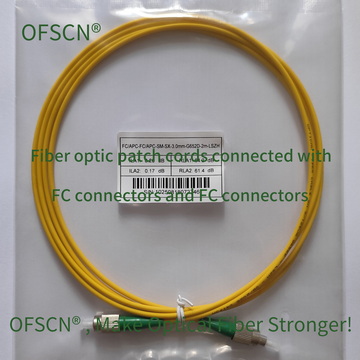
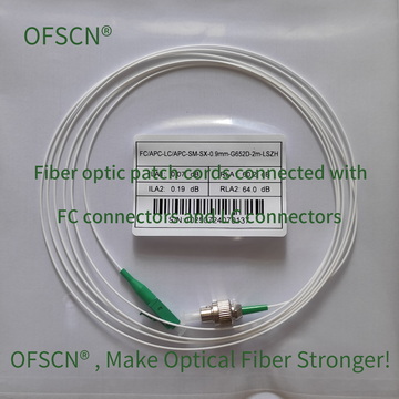
1. OFSCN® Standard Fiber Patch Cord
- Fiber Type: Default OFSCN® G.652D single-mode fiber (G.657, multimode, or polarization-maintaining fiber available for customization)
- Connector Specification: FC, ST, LC, SC (PC / APC selectable)
- Structural Parameters: Standard outer diameter 3\ \text{mm} ( 2\ \text{mm} , 0.9\ \text{mm} optional), manufactured with strict adherence to IEC fiber ferrule end-face geometric tolerances, ensuring high interchangeability and low insertion loss repeatability.
2. OFSCN® High Temperature Resistant Fiber Optic Adapter
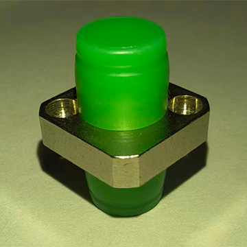
- Connector Type: FC/APC-FC/APC precision alignment ferrules, etc.
- Performance Characteristics: Utilizes high-precision ceramic alignment sleeves with strict inner diameter tolerance control, capable of withstanding temperatures up to 300\ ^\circ\text{C}, significantly reducing lateral eccentricity caused by loose sleeve fit.