Birleştirme yüzü neden 8 derecelik bir açıyla eğimli? Neden yeşil?
Fiber optic communication and fiber optic sensing fields use APC (Angled Physical Contact, angled physical contact) as a critical fiber end-face polishing process. Here are the answers to your two questions from the perspective of optical physics principles and international industry standards:
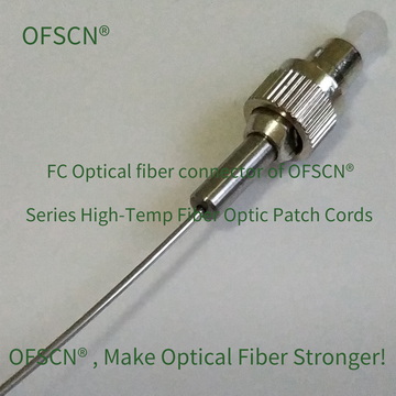
One: Why is the connector end-face polished at an 8^\circ angle?
This is primarily to minimize Return Loss (RL) to the greatest extent, preventing reflected light from interfering with laser light sources or Fiber Bragg Grating (FBG) demodulation equipment.
-
Altering the Path of Reflected Light:
During optical transmission, when light flows through the fiber end (i.e., the interface between silica glass and air), Fresnel Reflection occurs due to the sudden change in refractive index.- For flat PC or UPC connectors, the reflected light travels directly back into the fiber core, returning to the light source or demodulator along the original path. This can cause phase noise and instability in lasers, reducing the signal-to-noise ratio of sensing systems.
- For APC connectors, the end-face is polished at an 8^\circ angle. When light is reflected at the angled end-face, the reflected ray is angled relative to the fiber axis. This angle typically exceeds the critical angle for total internal reflection within the fiber core, so the reflected light cannot continue to propagate in the core and instead leaks into the fiber cladding to dissipate.
-
Why Specifically 8^\circ ?
8^\circ is the optimal balance angle determined through precise theoretical calculations and experimental validation:- If the polishing angle is too small (e.g., less than 5^\circ), some reflected light may still meet the conditions for total internal reflection and be guided backward in the core, reducing the effectiveness of echo loss suppression.
- If the polishing angle is too large (e.g., greater than 10^\circ), while return loss performance is better, it significantly increases the difficulty of mechanical alignment during connector mating, causes a substantial rise in Insertion Loss (IL), and adds complexity to manufacturing.
- For standard single-mode fibers (such as G.652.D, with a numerical aperture \text{NA} \approx 0.14), an 8^\circ angle is sufficient to allow almost all reflected light to escape the fiber core.
Note: After APC polishing, the connector’s return loss can be reduced to below -60\text{ dB} (meaning reflected light intensity is less than one in a million of the incident light), whereas flat-polished UPC typically has a return loss of -50\text{ dB}, and PC typically around -40\text{ dB}.
Two: Why is it green?
This is an international industry standard color coding (e.g., TIA-568 standard) established to prevent equipment damage or signal collapse due to accidental physical mismating.
-
Color Distinction Prevents Human Error:
- Blue (Blue): Represents single-mode PC/UPC (flat or micro-spherical polish) connectors.
- Green (Green): Represents single-mode APC (angled polish) connectors.
-
Severe Consequences of Mismating:
- If a blue UPC connector is accidentally plugged into a green APC adapter (or vice versa), because one end-face is flat and the other is angled, they will only achieve partial point contact upon physical mating, creating a large angled air gap between them.
- This results in extremely high insertion loss (typically greater than 3\text{ dB}) and poor return loss, rendering the optical path almost unusable.
- More seriously, due to uneven stress, the asymmetric collision can permanently scratch or physically damage expensive demodulator interfaces and sensor connectors.
- Using a uniform green housing (and green adapter flange) allows technicians to identify them at a glance from a distance and in complex field environments, thus preventing catastrophic misconnections.
Related Official OFSCN® (Da Cheng Yong Sheng) Products
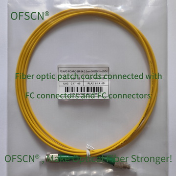
Da Cheng Yong Sheng (OFSCN®) manufactures various fiber optic patch cords, connectors, and Fiber Bragg Grating (FBG) sensors. In single-mode configurations, these products default to FC/APC (green) connectors to ensure high precision and low noise in optical measurements. They also offer various high-temperature customized models.
-
OFSCN® Standard Fiber Patch Cord: Standard single-mode fiber patch cords, which come by default with high return loss FC/APC connectors, providing excellent optical compatibility.
-
OFSCN® 120℃ Fiber Optic Connector: High-temperature resistant 120℃ fiber optic connectors, including various models such as FC/APC and SC/APC.
-
OFSCN® 300℃ Fiber Optic Connector: Professional industrial fiber optic connectors resistant to 300℃, supporting the FC/APC standard.