If the entire cable is accidentally broken during installation, does the whole cable need to be discarded and re-laid?
When a fiber optic cable accidentally breaks during construction, it is not always necessary to discard the entire cable and re-run it. The possibility and method of repair depend on the physical location of the break (transmission segment vs. sensing segment) and the type of cable structure and encapsulation.
I. Core Physical Principles of Fiber Optic Repair
After breaking, quartz fiber (primarily silicon dioxide \text{SiO}_2 ) can be reconnected using two main methods in optical engineering:
- Fusion Splicing:
This involves using a high-temperature electric arc generated by high-voltage discharge to fuse the cleanly cut end faces of two fibers together. For standard single-mode fibers (cladding diameter 125\ \mu\text{m} , core diameter 9\ \mu\text{m} ), the typical insertion loss of a high-quality fusion splice can be controlled to be below 0.05\text{ dB} , with excellent return loss, having almost no impact on optical signal transmission. - Mechanical Splicing:
This method uses a precision V-groove and an optical splicing cleave fluid for physical alignment and fixing. Typical insertion loss ranges between 0.1\text{ dB} \sim 0.5\text{ dB} . It is generally used for emergency repairs or temporary testing.
Therefore, from the perspective of optical transmission physics, fiber optics themselves are capable of being spliced and repaired.
II. Scenario-Based Assessment: Is a Full Replacement Necessary?
1. Break in the Transmission Cable or Pigtail Segment (Non-Sensing Functional Area): Full Replacement Not Required
If the break occurs in the transmission segment of the fiber optic cable, an outgoing pigtail, or a transmission trunk line without sensing elements:
- Method of Repair: Cut off the damaged ends, strip the coating/jacket, and use a fiber fusion splicer to splice the cores. A heat-shrink protective sleeve is then applied over the splice. For fiber optic cables with armored jackets, additional mechanical protection and sealing are provided using metal protective sleeves or fiber optic splice closures.
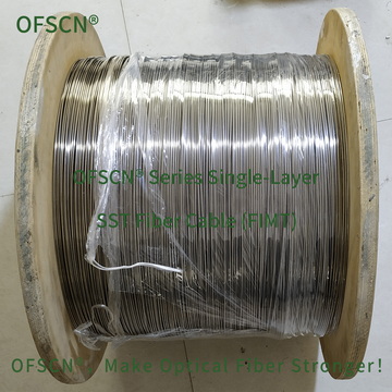
- Example Product: For communication and sensing fiber optic cables encapsulated in stainless steel tubes, such as the OFSCN® 300°C Seamless Steel Tube Fiber Cable, the internal fibers all support fusion splicing for connection and break termination. Applying protective sleeves after splicing does not affect downstream signal transmission.
2. Break within the Fiber Grating (FBG) Sensing Area or a Compact Sensor: The Damaged Segment Usually Needs Replacement
If the break occurs within the Fiber Bragg Grating sensor body or the core physical location of the grating region:
- Break Inside the Grating Area: The sensing principle of Fiber Bragg Gratings relies on periodic refractive index modulation. The Bragg wavelength is determined by the formula:\lambda_B = 2 n_{\text{eff}} \LambdaIf the break occurs within the grating area (where \Lambda is the grating period), field splicing will disrupt the continuity of the grating period and alter the local refractive index distribution, causing distortion or failure of the sensor’s wavelength spectrum, and the original factory calibration parameters cannot be restored.
- Break Within Structural Encapsulation: For strain sensors encapsulated in metal tubes or with interference pre-stress packaging, such as the OFSCN® Alloy Tube Packaged Fiber Bragg Grating strain sensor, the internal fiber is constrained by the matrix and has fixed factory wavelength/strain calibration coefficients (in units of \mu\varepsilon/\text{pm} ). Field disassembly of the metal tube for internal splicing makes it extremely difficult to ensure consistent physical stress transfer. In such cases, the damaged sensing unit must be cut off, and a new sensing connector segment needs to be replaced.

III. Recommended Diagnostic Steps for Field Engineering
- Locate the Break Point: Use an Optical Time Domain Reflectometer (OTDR) or a Visual Fault Locator (VFL) to accurately pinpoint the exact location of the construction break.
- Assess Loss and Optical Power Budget: After splice repair, use an optical power meter or a demodulator instrument to measure the link’s attenuation. As long as the total link loss is within the dynamic range of the fiber demodulator or transceiver (e.g., the optical dynamic range of the demodulator), it can be put into normal operation.