This article introduces the different environments of distributed optical fiber sensors and fiber Bragg grating sensors from multiple perspectives, and briefly compares the advantages and disadvantages of fiber Bragg grating sensing technology and distributed optical fiber sensing technology based on Raman scattering, Rayleigh scattering, and Brillouin scattering. Understanding these differences is important to choose the appropriate fiber sensing technology, and select OFSCN's corresponding series of fiber Bragg grating sensors or distributed optical fiber sensors.
This is a companion discussion topic for the original entry at https://www.ofscn.net/fbg-baike/294-application-difference.html
This is a high-level technical summary of the primary distinctions between Fiber Bragg Grating (FBG) sensing and Distributed Optical Fiber Sensing (DOFS). Choosing the right technology depends heavily on your specific engineering requirements and environmental constraints.
1. Key Technical Differences
- Measurement Topology:
- FBG (Quasi-Distributed): Focuses on specific “points.” It uses gratings inscribed at predetermined positions along the fiber. This is ideal when you have specific critical locations to monitor (e.g., specific joints in a bridge or points on a transformer).
- DOFS (Fully Distributed): Treats the entire fiber as a sensor. Based on scattering principles (Raman, Rayleigh, or Brillouin), it provides continuous data along the entire length. This is essential for leak detection in pipelines or perimeter security.
- Spatial Resolution vs. Distance:
- FBG systems offer extremely high-speed sampling (up to kHz or MHz) but are limited by the number of gratings per fiber.
- DOFS systems can cover tens of kilometers but typically have lower sampling frequencies and spatial resolutions ranging from centimeters (OFDR) to meters (DTS/BOTDA).
2. Environmental Considerations & Selection
The choice between these technologies often hinges on the thermal and mechanical environment:
- High-Temperature Environments: For temperatures up to 300°C or even 700°C, both technologies require specialized packaging.
- Mechanical Strain:
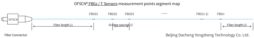
3. Visual Reference of OFSCN® Solutions
Below is a standard representation of how these sensors are structured for industrial environments, specifically focusing on the transition between sensing points and lead fibers:
When selecting a solution, it is vital to match the physical packaging to your installation method (e.g., surface-mounted, embedded, or welded). For detailed comparisons on specific scattering technologies (Raman vs. Rayleigh vs. Brillouin), you can refer to the full technical breakdown on our international site: OFSCN Knowledge Base.