Are the internal structures of the sensors the same when measuring 300 degrees and 100 degrees? Will selecting a larger size affect accuracy?
In Fiber Bragg Grating (FBG) sensing technology, there are fundamental differences in the internal structure and manufacturing process between sensors designed for measuring at 300 ℃ and those for measuring at 100 ℃. Regarding whether “selecting a larger measurement range affects accuracy,” the mechanism differs from traditional electronic sensors and requires objective analysis from two perspectives: the wavelength demodulation mechanism and the temperature calibration model.
I. Internal Structure Differences Between 300 ℃ and 100 ℃ Sensors
The physical measurement range of an FBG temperature sensor is not simply set by software but is determined by the material’s physical tolerance limits and its thermodynamic structure. The core structural differences between the two primarily lie in the following aspects:
-
Fiber Coating Material:
- 100 ℃ Specification: The fiber coating typically uses standard UV-curable acrylate. This material softens, ages, degrades, or even carbonizes when exposed to environments exceeding 85 ℃ ~ 100 ℃, causing the protective coating to fail and the quartz fiber to become brittle and break.
- 300 ℃ Specification: High-temperature resistant polyimide coating must be used, or the coating may be stripped entirely and replaced with specialized metallic or suspended protection. Polyimide can withstand high temperatures from -200 ℃ to 300 ℃ (instantaneously higher), ensuring the mechanical integrity of the underlying quartz fiber remains stable.
-
High-Temperature Annealing Process for Gratings:
- Standard gratings written using UV photosensitive methods (Type I gratings) experience thermal decay of their refractive index modulation at high temperatures.
- FBGs for the 300 ℃ specification must undergo rigorous high-temperature pre-annealing before packaging to release unstable color center defects prematurely. This guarantees that the central wavelength does not undergo irreversible permanent drift during long-term operation at 300 ℃. In contrast, the annealing temperature and time requirements for 100 ℃ gratings are comparatively lower.
-
Stress-Free Packaging Structure and Auxiliary Fixing Materials:
- To ensure FBG temperature sensors respond only to temperature without interference from structural deformation or external stress, the internal grating region requires “stress-free packaging.”
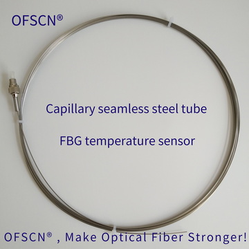
- As the temperature rises to 300 ℃, the thermal expansion displacement of the outer protective micro-tube (e.g., 316L seamless stainless steel tube) becomes significant. The 300 ℃ sensor must incorporate sufficient thermal compensation space for free sliding. Furthermore, the end-cap adhesive or sealing solder must withstand the thermal cycling stresses at 300 ℃, imposing far higher structural and process requirements than for 100 ℃ sensors.
II. Does Selecting a Larger Measurement Range Affect Measurement Accuracy?
The answer is: While physical resolution does not degrade, there are differences in calibration fitting accuracy and multiplexing capacity.
1. Physical Resolution Perspective (Fundamental Difference from Electrical Sensors)
For traditional analog electrical sensors (like thermocouples or resistance thermometers paired with ADC acquisition modules), increasing the measurement range from 100 ℃ to 300 ℃, with a fixed ADC bit depth, results in a larger temperature span per LSB, directly degrading effective resolution and accuracy.
However, FBG is a wavelength-modulated sensor. The Bragg reflection wavelength satisfies the physical equation:
\lambda_B = 2 n_{\text{eff}} \Lambda
Its temperature sensitivity, S_T = \frac{\Delta \lambda_B}{\Delta T}, is primarily determined by the thermo-optic and thermal expansion coefficients of silica, approximately 10\ \text{pm/}^\circ\text{C} from room temperature to the micron band. FBG demodulators identify the absolute wavelength position of the reflection peak (typically with a fixed instrument resolution of 1\ \text{pm} or 0.1\ \text{pm}). The measurement resolution of the demodulator does not decrease with changes in the sensor’s measurement range.
2. Calibration Model and Fitting Error Perspective (Slight Impact)
- Calibration Formula Order: Within the range of room temperature to 100 ℃, the FBG’s temperature-wavelength response is highly linear. Factory calibration usually employs a first-order linear equation (term units are ^\circ\text{C/pm}).
- When the temperature range expands to 300 ℃, the non-linear effects of silica’s thermo-optic coefficient become more pronounced, necessitating the use of a second-order polynomial (binomial calibration formula) for fitting:
T = A \cdot (\Delta \lambda)^2 + B \cdot \Delta \lambda + C
- If the binomial parameters calibrated for a 300 ℃ span are used to calculate small temperature differences within the 0 ℃ to 100 ℃ range, the measurement accuracy (especially local absolute error in the room temperature range) may be slightly inferior compared to a sensor specifically calibrated linearly within the narrow 0 ℃ to 100 ℃ range. This is due to the fitting residuals of the large-span non-linear polynomial within the local interval.
3. Spectral Resource and Multiplexing Test Point Occupation
For every 100 ℃ increase in temperature, the FBG’s central wavelength shifts redward by approximately 1\ \text{nm}:
- When measuring at 100 ℃, the single-point wavelength variation range is about 1\ \text{nm}.
- When measuring at 300 ℃, the single-point wavelength variation range expands to over 3\ \text{nm}.
To prevent wavelength aliasing, 300 ℃ sensors require a larger safety channel interval in the spectrum, directly reducing the number of test points that can be serially connected within a limited spectral bandwidth (e.g., a typical 40nm demodulator).
III. Official Reference Product Specifications
Beijing Dacheng Yongsheng Technology Co., Ltd. (OFSCN®) employs corresponding structural designs and calibration processes for different measurement range intervals:
-
For scenarios within 100 ℃:
Uses a single-layer seamless steel tube micro-structure package, providing a first-order calibration formula from room temperature to 100 ℃.
OFSCN® 100°C Fiber Bragg Grating Temperature Sensor
-
For scenarios within 300 ℃:
Uses high-temperature resistant polyimide fiber and annealed gratings, providing a binomial temperature-wavelength calibration formula from room temperature to 300 ℃.
OFSCN® 300°C Fiber Bragg Grating Temperature Sensor

Selection Recommendation: If the actual operating conditions absolutely do not exceed 100 ℃, it is recommended to prioritize the 100 ℃ specification for a more precise linear fit and higher channel multiplexing efficiency. If the operating conditions have potential for over-temperature or the target temperature is between 100 ℃ and 300 ℃, the 300 ℃ specification must be chosen to ensure the sensing element and coating do not suffer thermal degradation.