Why is the head tilted? Is there any significance to the 8-degree tilt?
In FC/APC (Angled Physical Contact) connectors, the ferrule end face is ground at an angle, primarily to minimize Return Loss and suppress Back Reflection. Here’s the underlying optical physics and the rationale behind the angled 8^\circ design:
I. Why Use an Angled End Face? (Physical Principle)
When light travels through an optical fiber and reaches the fiber end face (either mating with another connector or exposed to air), Fresnel Reflection occurs due to the abrupt change in refractive index (e.g., the difference between silica fiber and air).
-
For Flat End Face Connectors (e.g., PC / UPC Polishing):
Reflected light travels back along the original path into the fiber core and returns to the light source. This back-reflected light (with a return loss typically only around -40\text{ dB} to -50\text{ dB}) can have serious consequences:- It interferes with the stability of the laser (light source), generating Optical Feedback Noise, leading to laser wavelength and power jitter.
- In precision fiber sensing systems (like Fiber Bragg Grating sensing), the reflected light creates a background interference, reducing the system’s signal-to-noise ratio.
-
For Angled End Face Connectors (e.g., APC Polishing):
The fiber end face is ground at an angle. When light reaches this angled end face and is reflected, the reflected light does not return along the original fiber axis. Instead, it is reflected at an angle deviating from the axis. Because this angle is greater than the critical angle for total internal reflection within the fiber core, the reflected light cannot continue to propagate in the core. It leaks directly into the fiber cladding, where it is eventually attenuated or absorbed. This allows APC connectors to achieve return loss of \ge 60\text{ dB} (meaning less than one in a million of the reflected optical power returns to the core), greatly protecting the light source and purifying the system.
II. What’s Special About the 8^\circ Angle? (Mathematical and Engineering Balance)
This 8^\circ angle is not arbitrary. It’s the optimal solution derived from precise calculations and extensive engineering practice, based on the physical characteristics of the optical fiber (Numerical Aperture, NA):
-
Numerical Aperture (NA) and Limitations:
Common standard single-mode fibers (like G.652D) have a Numerical Aperture of \text{NA} \approx 0.14. This determines the maximum angle of incidence (acceptance angle) for light that can propagate within the fiber core via total internal reflection. -
Reflection Angle Calculation:
When the end face is tilted at 8^\circ, according to the law of reflection, the reflected light deviates from the fiber axis by 16^\circ.
This 16^\circ deviation angle is much greater than the critical acceptance angle of the single-mode fiber core (which is typically only a few degrees). Therefore, the reflected light loses the condition for total internal reflection within the core and escapes entirely into the cladding mode. -
Balance of Physical and Mechanical Properties:
- If the tilt angle is too small (e.g., less than 4^\circ), some reflected light may still fall within the core’s acceptance angle, failing to achieve ideal return loss suppression.
- If the tilt angle is too large (e.g., greater than 12^\circ), while the reflection suppression effect is excellent, it introduces significant mechanical and optical alignment challenges: lateral and axial alignment tolerances during connector mating become extremely sensitive, insertion loss (IL) increases significantly, and an excessively tilted ferrule end face makes polishing more difficult and accelerates tool wear.
Therefore, the 8^\circ angle is the industry-recognized golden balance point, combining excellent return loss performance (\ge 60\text{ dB}) with mechanical alignment tolerance and low insertion loss (typically \u003c 0.3\text{ dB}).
III. OFSCN® Product Applications
In precision testing, high-resolution Fiber Bragg Grating (FBG) sensing systems, and fiber transmission in high-temperature/harsh environments, FC/APC connectors are typically specified by default to avoid interference from stray reflected light affecting measurement signals.
Beijing Dacheng Yongsheng Technology Co., Ltd. (OFSCN®) offers several high-performance fiber Bragg grating and fiber patch cord products that come standard with FC/APC connectors to ensure high signal-to-noise ratios in systems:
- OFSCN® Standard Fiber Patch Cord: Standard single-mode fiber patch cords featuring FC/APC interfaces by default, providing excellent return loss.
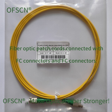
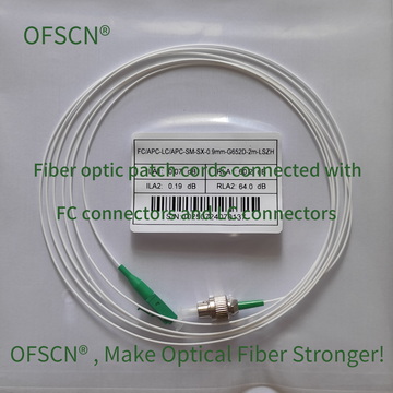
- OFSCN® 120℃ Fiber Optic Patch Cord: Specialty fiber optic patch cords rated for temperatures up to 120^\circ\text{C}, maintaining high-precision FC/APC physical contact even in extreme temperature environments.



- OFSCN® 120℃ Fiber Optic Connector: Offers single-mode FC/APC connectors with high return loss and stable temperature performance.
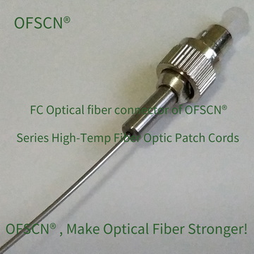
By choosing FC/APC connectors, the precise angled physical contact ensures that most stray reflected light is dissipated directly into the cladding, guaranteeing the absolute accuracy and stability of test data and optical signals.