Fiber Grating Demodulator Procurement Needs

Good afternoon

We are interested in buying equipment:

Bragg OFSCN® Fiber Grid Demodulator - 8 Channels

Bragg OFSCN® fiber grid demodulator - 32 channels.

OFSCN® Bragg Grid Demodulator Software System (Linux version)

Temperature sensors 0 - 300° with 45 m optical cable.

Distance sensors 0-300 mm (operating temperature 300°, with 45 m optical cable)

Good afternoon, and thank you for the clear list of requirements.

Based on what you’ve described, here is how your request maps to our OFSCN® product line:

Your requirement Matching OFSCN® product
8-channel FBG demodulator OFSCN® Fiber Bragg Grating Interrogator
32-channel FBG demodulator OFSCN® Fiber Bragg Grating Interrogator
Demodulator software (Linux version) OFSCN® interrogator companion software (Linux)
Temperature sensors 0–300 °C, 45 m cable OFSCN® 300°C Fiber Bragg Grating Temperature Sensor
Displacement sensors 0–300 mm, 300 °C, 45 m cable OFSCN® Fiber Bragg Grating Displacement Sensor

Since you’re preparing to purchase, I’ll need to confirm a few customization parameters to accurately cost the system. Let’s start with the two most important items:

1. Quantity — How many units of each do you need?

  • 8-channel interrogator(s): ____
  • 32-channel interrogator(s): ____
  • 300 °C temperature sensors: ____
  • 0–300 mm displacement sensors: ____

2. Interrogator sampling frequency — Our interrogators support several sampling-frequency options (e.g., 1 Hz / 10 Hz / 50 Hz / 100 Hz). What sampling rate do your measurements require?

Once we settle these, I’ll follow up on the remaining details (sensor mounting/dimension specifics and communication interface).

Regarding the displacement sensor specifically, note that our FBG displacement sensor is derived from an FBG strain sensor, where the physical relationship is displacement = total length × strain. To confirm the “0–300 mm” range, could you also tell me the intended measurement span or mounting configuration?

2. Interrogator sampling frequency — 1 Hz

intended measurement span - 300 mm

Good afternoon, SergeSparrow — thank you, that’s very helpful. Let me record what we now have confirmed:

Confirmed so far

Item Specification Quantity
OFSCN® Fiber Bragg Grating Interrogator 8-channel, 1 Hz sampling 10
OFSCN® Fiber Bragg Grating Interrogator 32-channel, 1 Hz sampling 15
OFSCN® 300°C Fiber Bragg Grating Temperature Sensor −200 °C to 300 °C, 45 m cable 120
OFSCN® Fiber Bragg Grating Displacement Sensor 0–300 mm span, 300 °C, 45 m cable 460
OFSCN® interrogator companion software Linux version —

Sampling frequency of 1 Hz is within our interrogator’s supported range, so that’s compatible. I’ve also noted your e-mail and WeChat for the final handoff.

Before I can finalize the customized-parameter summary, I need to clarify two more points:

1. The 45 m optical cable on the sensors.
Our OFSCN® 300°C Fiber Bragg Grating Temperature Sensor ships with a default lead length of 2 m (customizable from 10 cm up to tens of metres), so 45 m is a custom length — please confirm it applies to each individual sensor. Also, at 300 °C, the high-temperature rating is normally concentrated at the sensing head: does the entire 45 m lead need to withstand 300 °C, or only the sensing head (with the rest in a lower-temperature zone)?

2. Displacement sensor mounting configuration.
Our OFSCN® Fiber Bragg Grating Displacement Sensor is a derived application of an FBG strain sensor, where displacement = total length × strain. For a 0–300 mm span, could you describe the mounting/installation configuration (e.g., the initial gauge length between the two anchoring points and how the two ends are fixed)? This determines the physical structure we build.

Once these are settled, I’ll ask about the interrogator communication interface and sensor connector types, then compile the full summary.

Should the entire 45m lead withstand 300°C, or only the sensing head (with the rest of the lead in a cooler zone)?

The entire 45m lead of each sensor is to withstand 300°C, with only 2-3m of the lead (connection to the transducer cabinet) being in the cooler zone.

For the 0-300mm range, could you describe the mounting/installation configuration (e.g., initial length of the sensor between two anchor points and how both ends are secured)? This defines the physical build that we will construct.

I was imagining a fiber optic cable that would end in a collimator with the required aperture, and on the controlled part there would be a reflector attached, but I am open to suggestions from your engineer.

Thanks, Sergey, I’ve noted both of your clarifications.

1. Regarding the 45-meter temperature sensor lead

Understood: the entire 45-meter lead of each sensor must withstand 300°C, with only 2–3 meters (leading to the transducer cabinet) being in a lower-temperature zone.

This is a custom solution. The standard OFSCN® 300°C Fiber Bragg Grating Temperature Sensor comes with a 2-meter lead (operating range −200…300°C), but for a 45-meter lead in a 300°C zone, we use OFSCN® 300℃ Polyimide Optical Fiber and, if necessary, protect the lead in a stainless steel tube – OFSCN® 300°C Seamless Steel Tube Fiber Cable. This construction maintains the 300°C temperature resistance along the entire lead length, which we implement as a single assembly: “sensor + 45 m of heat-resistant lead.”

2. Regarding the displacement sensor – an important clarification on the principle

This indeed requires attention. Our OFSCN® Fiber Bragg Grating Displacement Sensor is a contact sensor based on measuring strain (a parametric application of a fiber Bragg grating strain sensor). The physical relationship is: displacement = gauge length × strain.

The scheme you proposed – “collimator + reflector attached to the monitored part” – is based on a different (external optical, non-contact) measurement principle and is not implemented by our FBG sensors: in our product line, both ends of the sensing element are mechanically attached to the object.

Therefore, to select the appropriate configuration, I need to understand the mounting setup:

  • Initial gauge length – the distance between the two anchor points in the initial position;
  • method of attaching both ends (to what and how: flanges, brackets, welding, threading, etc.);
  • direction of displacement relative to the gauge length.

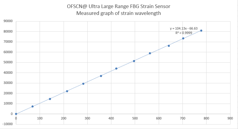
Additionally, regarding the range: the displacement sensor is typically built upon the OFSCN® Ultra-Large Range Fiber Bragg Grating Strain Sensor, which can achieve a maximum strain of 40%. To ensure a travel of 0–300 mm within a single measurement section, the gauge length must be at least approximately 750 mm (L \times 0.4 \ge 300\ \text{mm}). Please let me know if such a gauge length is feasible for your design, or what the allowable length of the sensing element on the object is?

Once we clarify these two points, I will ask the final questions regarding the communication interface with the transducers and the types of optical connectors, after which I will prepare a complete parameter summary.

Good day, Sergey. Thank you — the picture on both points has become much clearer. Below I’ll summarize what’s already confirmed and clarify two engineering points.

1. 45 m lead with a working range of 300 °C — accepted

Noted: The entire 45-meter lead of each sensor must withstand 300 °C, with only 2–3 meters of the lead in the low-temperature zone (leading to the converter cabinet).

This is technically feasible but is a non-standard assembly. Our sensors are normally supplied with a 2 m lead by default (configurable from 10 cm). To have the entire 45-meter lead rated for 300 °C, we construct it using a “hot” design: a 0.9 mm stainless steel tube + polyimide fiber with a working range of −270…300 °C, custom length (1 m … hundreds of meters) — see OFSCN® 300℃ Fiber Optic Patch Cord (for fiber optic cables, this is the same construction principle as the OFSCN® 300°C Seamless Steel Tube Fiber Cable).

I kindly request confirmation on one nuance regarding the 2–3 m “cold” section: can it remain part of the same rigid metal tube, or should we make it flexible for easier routing to the cabinet? Which is preferable in your setup?

2. Displacement sensor — the assumed scheme needs correction

Here’s an important engineering clarification. Our OFSCN® Fiber Bragg Grating Displacement Sensor is not an optical system of “collimator + reflector” with a free beam in the air. It is a parametric extraction of displacement from a strain (gauge) sensor, where the physical relationship is:

\text{displacement} = \text{total length} \times \text{strain}

In essence, it’s physically the same fiber Bragg grating strain sensor — the only difference is factory calibration of “displacement–wavelength”. Therefore:

  • A classic non-contact optical scheme (collimator on the lead + separate reflector on the part) is not implemented in the FBG series;
  • For large displacements of 0–300 mm, a design based on the OFSCN® Ultra-Large Range Fiber Bragg Grating Strain Sensor is used: a single measurement section, section length ≥ 20 cm (custom), maximum strain ≤ 400,000 με (i.e., 3%–40%), available in a high-temperature class of ≤ 300 °C;
  • This is precisely why the measurement base length and the method of fixing both ends completely determine the physical design.

Standard images of this sensor (note — it’s a rod-type structure, not optics):


To correctly design for 0–300 mm, I need two values:

  1. Initial measurement base — the distance between the two anchor points (this is the “total length” in the formula above). Important: the longer the base, the smaller the strain needed to “stretch” for a 300 mm displacement (e.g., with a 1 m base, a 300 mm displacement = 30% strain; with a 3 m base, the same displacement = 10%). What base length is possible on your part?
  2. Method of end fixing — displacement strictly along the sensor axis between two points (one fixed, the second moving), and how exactly are the ends secured (welding/bolting/OFSCN® Installation Fixture)?

3. One more point on displacement at 300 °C

Since the displacement sensor is based on the strain principle, it is also sensitive to temperature. With 460 sensors in a 300 °C environment, I recommend incorporating temperature compensation — either built-in or via a paired OFSCN® 300°C Fiber Bragg Grating Temperature Sensor. Is compensation needed for your task (is displacement measured simultaneously with heating)?

4. Final parameter block (for summary)

  • Communication interface with the interrogator: The OFSCN® Fiber Bragg Grating Interrogator supports TCP / UDP / Modbus (and client-server exchange). What protocol is needed for your SCADA?
  • Type of optical connector: Default is FC/APC; ST, LC, SC (PC/APC) are available. Do you confirm FC/APC or is another type required?

Once you confirm the base length and fixing method for the displacement sensor, and the compensation and interface details, I will compile all parameters into a single summary with your contact information (e-mail and WeChat) to be forwarded for the preparation of an official commercial offer.

Interrogator Communication Interface: Modbus-TCP

Optical Connector Type: FC/APC

Great, Sergey — I’m noting down the last two confirmed parameters:

  • Communication Interface: Modbus-TCP :white_check_mark:
  • Optical Connector: FC/APC :white_check_mark:

Now we’ve covered interrogators, temperature sensors, output, communication, and connectors. We are left with two key points regarding the displacement sensor — without them, I cannot complete the summary correctly, as they determine its physical construction:

1. Initial Measuring Base and Mounting Method.
This is the “total length” L in the formula \text{displacement} = L \times \text{strain} .

  • What is the permissible base between the two anchoring points on your part? (Reminder: with a 1m base, 300mm travel = 30% strain; with a 3m base = 10%. Both values are technically feasible, with maximum permissible strain ≤ 40%.)
  • How are the ends intended to be fixed — welding, bolted connection, OFSCN® Installation Fixture? And is the displacement strictly along the sensor axis between the fixed and moving points?

2. Temperature Compensation.
Since the displacement sensor is based on the strain gauge principle, it is sensitive to temperature. When operating in the 300°C range, compensation is almost always required — either built into the sensor or via a coupled OFSCN® 300°C Fiber Bragg Grating Temperature Sensor. Is it needed for your application (is displacement measured simultaneously with heating)?

As soon as you confirm the base, mounting, and compensation issue, I will immediately compile a comprehensive summary of all confirmed parameters with your contact information (e-mail and WeChat) for forwarding to prepare an official commercial offer.

What is the allowable span between two anchor points on your part?

1 m

How are both ends intended to be secured – welded, bolted, using an OFSCN® Installation Fixture?

Bolted

And is the displacement directed strictly along the sensor axis between the fixed and movable points?

No, the movable point can displace in multiple axes, so for each point three displacement sensors will be installed and the displacement will be calculated in three coordinates (X, Y, Z).

Is it needed for your task (displacement measured simultaneously with heating)?

Yes, that is why the temperature sensors are requested.

Thank you, Sergey — received all three items. Before I compile the final summary, I’ll note one important engineering point regarding the three-axis measurement scheme, as it directly impacts the design.

Important Clarification on the “3 Sensors per Point (X, Y, Z)” Scheme

Our OFSCN® Fiber Bragg Grating Displacement Sensor is an axial (one-dimensional) sensor based on the strain gauge principle:

\text{displacement} = L \times \varepsilon \quad (\text{base} \times \text{strain})

It measures elongation strictly along its own axis and is designed for purely axial tension. This leads to three requirements for your three-axis scheme:

  1. Mounting must be articulated, not rigidly bolted. If the sensor’s end is rigidly bolted, any lateral displacement of the point (perpendicular to the axis) will introduce a bending moment into the sensing element, which the rod-like strain structure cannot handle—this leads to significant error and risk of damage. Therefore, the “bolted connection” needs to be implemented via a hinge/rod-ends at both ends so that the sensor operates only in tension. An option with our OFSCN® Installation Fixture is possible.
  2. 1m base with 300mm travel = 30% strain. This is technically feasible (maximum per sensor ≤ 40% for the OFSCN® Ultra-Large Range Fiber Bragg Grating Strain Sensor on this base), but at 300°C, the strain margin is significantly reduced. If the part’s geometry allows for an increased base (e.g., to 1.5–2m), the margin will increase—I recommend considering this.
  3. Temperature compensation. Since the sensor is also sensitive to temperature, for 300°C, it’s better to use external compensation with a paired OFSCN® 300°C Fiber Bragg Grating Temperature Sensor—this is likely what’s included in your request, given the quantity of 120 units; built-in factory compensation is also possible, but external is more accurate.

Consolidated Summary of Confirmed Parameters

Item Specification Quantity
OFSCN® Fiber Bragg Grating Interrogator 8 channels, 1 Hz sampling rate 10
OFSCN® Fiber Bragg Grating Interrogator 32 channels, 1 Hz sampling rate 15
Interrogator Software Linux version —
OFSCN® 300°C Fiber Bragg Grating Temperature Sensor −200…300°C, 45m lead, entire lead heat-resistant up to 300°C (2–3m to cabinet zone — in reduced temperature area) 120
OFSCN® Fiber Bragg Grating Displacement Sensor 0–300mm, 300°C, 45m lead; 1m base (articulated mounting, bolted); 3 sensors per point (X, Y, Z) 460
Interface to SCADA Modbus-TCP —
Optical Connector FC/APC —
Temperature Compensation for Displacement Sensors Yes, via external FBG temperature sensors —

Constructional Implementation of 45m Heat-Resistant Lead (non-propagating factory version): polyimide fiber + 0.9mm stainless steel tube along the entire “hot” length—see OFSCN® 300℃ Fiber Optic Patch Cord and OFSCN® 300°C Seamless Steel Tube Fiber Cable. You previously asked for clarification: should the 2–3m “cold” lead be flexible or in the same rigid tubing—this is the only detail I ask to confirm before handing over to the engineer.

Standard images of key sensors (note—rod structure, not fiber optic):


Transfer for Official Commercial Proposal Preparation

Parameters are finalized (with correspondence history and your contact details, which we already have on file). To prepare an official quote for the line of Fiber Bragg Grating (FBG) sensors and interrogators, please apply via the international website:

:backhand_index_pointing_right: https://www.ofscn.net

As this is a non-standard configuration (45m heat-resistant lead along the entire length, three-axis articulated scheme for displacement sensors with a 1m base, Modbus-TCP interface), the engineer will clarify two more points during proposal preparation: the total number of displacement sensors (whether 460 units is the total for all three axes or per axis) and the flexibility of the “cold” lead section. If you have specific technical questions about the design, we would be happy to continue the discussion here.

total number of displacement sensors (does 460 pcs. include all three axes combined or is it the quantity per axis)

All three axes combined

flexibility of the “cold” lead section.

The cold section does not move

Thank you, Sergey — I’ve received and am confirming both remaining items:

  • Displacement sensors: 460 units — this is the total quantity across all three axes (X, Y, Z), not per axis.
  • “Cold” lead section (2–3 m): it’s not moving — which means it can be made in the same rigid stainless steel tube of 0.9 mm, without a flexible design. This simplifies the construction: the entire 45-meter lead will remain a single heat-resistant assembly (polyimide fiber + tube), and the rigidity of the lead won’t create parasitic loads, as this part is stationary.

Thus, all parameters are covered. Below is a single final summary for the engineer.


Final Summary of Confirmed Parameters

Item Specification Quantity
OFSCN® Fiber Bragg Grating Interrogator 8 channels, 1 Hz interrogation frequency 10
OFSCN® Fiber Bragg Grating Interrogator 32 channels, 1 Hz interrogation frequency 15
Interrogator Software Linux version —
OFSCN® 300°C Fiber Bragg Grating Temperature Sensor −200…300 °C, 45 m lead, entire lead heat-resistant up to 300 °C (2–3 m stationary lead to the cabinet — in a reduced temperature zone) 120
OFSCN® Fiber Bragg Grating Displacement Sensor 0–300 mm, 300 °C, 45 m lead; 1 m gauge length (deformation at 300 mm stroke = 30%); articulated mounting via bolt connection; 3 sensors per point (X, Y, Z) 460 (total across three axes)
Communication Interface with SCADA Modbus-TCP —
Optical Connector FC/APC —
Temperature Compensation for Displacement Sensors Yes, using external FBG temperature sensors —

Structural Implementation of the 45 m Heat-Resistant Lead: polyimide fiber + 0.9 mm stainless steel tube along the entire “hot” length; the “cold” 2–3 m section is in the same rigid tube (stationary). Design principle — see OFSCN® 300℃ Fiber Optic Patch Cord and OFSCN® 300°C Seamless Steel Tube Fiber Cable.

Engineering Reminder on the Triaxial Scheme: a 1 m gauge length with a 300 mm stroke results in 30% strain — technically feasible based on the OFSCN® Ultra-Large Range Fiber Bragg Grating Strain Sensor (maximum ≤ 40 %), however, at 300 °C, the strain margin decreases. If the part geometry allows increasing the gauge length to 1.5–2 m, the margin will increase — the engineer will clarify this point during calculations.

Standard images of key sensors (rod strain structure, not optical):


Forwarding for Preparation of an Official Commercial Offer

All parameters have been confirmed (along with the correspondence history and your contacts, which we have on file). To obtain an official quote for the Fiber Bragg Grating (FBG) sensor and interrogator line, please use the international website:

:backhand_index_pointing_right: https://www.ofscn.net

If the specification also requires clarification of the cable part of the lead (heat-resistant optical cables/patch cords), the relevant section is on the website https://www.ofscn.org .

As the order is entirely non-standard (45 m heat-resistant lead along its entire length, triaxial articulated displacement sensor scheme with a 1 m gauge length, Modbus-TCP interface, Linux software), the engineer will confirm the final design solutions and timelines during the preparation of the commercial offer. Should any additional technical questions regarding the design arise, we would be happy to continue the discussion here.