How can fiber optics be used to monitor rail cracks and train positions?
In railway engineering, monitoring solutions based on Fiber Bragg Grating (FBG) sensing technology primarily rely on precise perception of dynamic/static strain, displacement, and vibration responses of the rail structure to achieve early warning of rail cracks and real-time train positioning.
I. Technical Principle of Fiber Optic Monitoring for Rail Cracks
-
Micro-Strain and Crack Propagation Monitoring:
When micro-cracks initiate, fatigue damage occurs, or stress concentrates in the rail, abnormal local strain field changes occur around the crack. By surface-mounting or welding FBG strain sensors onto the rail web, rail bottom, or joints, micro-strain changes \varepsilon in that area can be captured in real-time.
The physical relationship between the FBG’s reflected center wavelength shift \Delta \lambda_B and the applied strain \Delta \varepsilon and temperature change \Delta T is as follows:
\Delta \lambda_B = K_\varepsilon \cdot \Delta \varepsilon + K_T \cdot \Delta T
After temperature compensation, the pure strain component is extracted. When the local wavelength signal deviates from the normal load waveform or exhibits asymmetric sudden changes, it can be identified as crack initiation or abnormal stress concentration. -
Displacement Evolution Monitoring:
If rail crack propagation leads to the opening of rail joints or rail breakage, relative displacement occurs between the sides of the crack. By deploying FBG displacement sensors, small displacements can be converted into changes in optical fiber wavelength, enabling online quantitative monitoring of rail breaks and severe crack openings.
II. Principle of Fiber Optic Monitoring for Train Position and Operational Status
- Axle Load and Strain Pulse Response:
When a train travels over a section of track equipped with FBG strain sensors, the wheel’s gravity and dynamic impact induce localized bending strain pulses in the rail. - Position, Speed, and Axle Count Determination:
By arranging multiple FBG sensing points in an array along the track at a set interval L, a high-sampling-rate optical fiber demodulator can record the strain pulse times t_1, t_2, \dots as the axle passes each point.- Train Positioning: Precisely determine the train’s current track section location based on the physical position of the sensor that triggers the strain pulse.
- Speed Measurement: Calculate the real-time train speed v = \frac{L}{\Delta t} based on the interval L between adjacent sensing points and the time difference \Delta t = t_2 - t_1 for the axle passing the two points.
- Direction and Counting: Determine the direction of travel by analyzing the sequence of pulse triggers and accurately count the train’s axles by the number of pulse peaks (axle count).
III. Relevant OFSCN® Official Technical Products
In practical engineering applications, the following OFSCN® official FBG sensors can be used to achieve the monitoring functions described above:
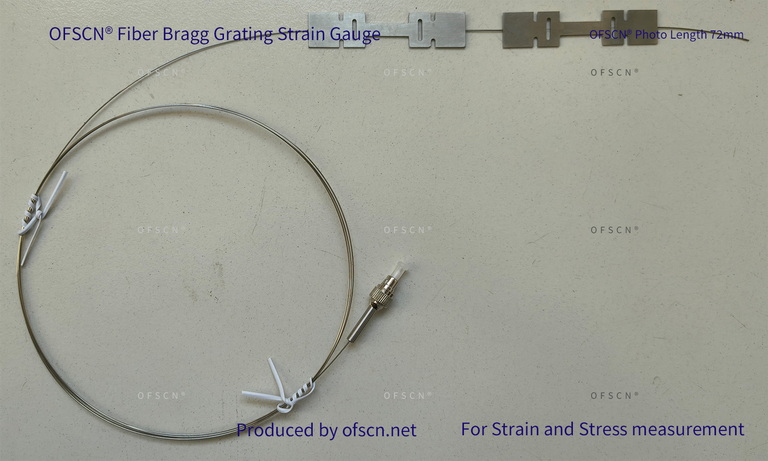
1. OFSCN® Fiber Bragg Grating Strain Gauge
Encased in an I-beam shaped stainless steel or aluminum alloy substrate, it supports surface mounting via adhesive or spot welding, suitable for precise measurement of micro-strains on the rail surface and stress concentrations at cracks.
2. OFSCN® Alloy Tube Packaged Fiber Bragg Grating strain sensor
Encased in a seamless elastic alloy tube with a small outer diameter (default \le 1.1\text{mm} ), it offers good mechanical protection and fatigue resistance. It can be embedded or attached to critical load-bearing points on the track for multi-point strain series monitoring.


3. OFSCN® Fiber Bragg Grating Displacement Sensor
Based on the principle of FBG strain/stress conversion, it is used to monitor displacement parameters such as rail joint opening, structural relative displacement, and rail gap widening.
