How much light is reflected back at a connector?
To accurately measure how much light is reflected by fiber optic connectors, the metrics of “Return Loss” (RL) or “Reflectance” are typically used in physics and optical engineering for quantitative characterization and measurement.
I. Physical Concepts and Definitions
When light travels through an optical fiber and encounters a sudden change in the refractive index of the medium (such as the physical contact surface where two fibers are joined), a portion of the light energy is reflected back towards the light source. This phenomenon is known as Fresnel Reflection.
- Return Loss (RL): Defined as the logarithmic ratio of incident optical power to reflected optical power, expressed in decibels (dB). Its mathematical expression is:\text{RL} = -10 \log_{10} \left( \frac{P_r}{P_i} \right)Where P_i is the incident optical power and P_r is the reflected optical power.
Note: Return Loss is typically expressed as a positive value in engineering (e.g., 60\ \text{dB} ). A higher Return Loss value indicates less reflected light, signifying superior physical contact and transmission performance of the connector.
II. Two Main Methods for Measuring Connector Reflected Light
In laboratories and on-site engineering, the following two technical approaches are primarily used to measure the amount of light reflected by connectors:
1. Optical Continuous Wave Reflectometry (OCWR) – “Return Loss Meter” Testing
This is the core working principle of a Return Loss Tester, mainly used for factory testing and quality certification of optical components.
- Measurement Mechanism:
- The tester integrates a stable continuous wave (CW) laser light source (SLS), a high-sensitivity optical power meter (OPM), and an optical directional coupler (or circulator).
- The stable light source emits light with a known power P_i , which is directed into the connector under test via the coupler.
- The reflected optical power P_r from the connector end-face is guided to the optical power meter through the coupler.
- After reference calibration (to eliminate system errors from the test cable), the device automatically calculates and outputs the return loss of the connector.
- Key Engineering Operation (Eliminating Far-End Interference):
To prevent the Fresnel reflection from subsequent fiber end-faces (breaks) from being superimposed, the fiber optic cable behind the connector under test must be subjected to Mandrel Wrapping during testing. This involves winding the fiber several times around a cylindrical object with a diameter of approximately 5\ \text{mm} to 10\ \text{mm} . This causes the light traveling further to be completely attenuated due to leakage at the bends, ensuring that only the reflection from the target connector is detected.
2. Optical Time Domain Reflectometer (OTDR)
This is the most commonly used multi-point measurement method in fiber optic link installation and maintenance fields.
- Measurement Mechanism:
- The OTDR injects high-power optical pulses into the fiber optic cable under test and rapidly collects the backscattered Rayleigh scattering and Fresnel reflection signals that return over time.
- On the OTDR’s trace curve, the location of a fiber optic connector appears as a sharp upward reflection peak.
- The instrument’s software automatically calculates the reflectance of the connector at that specific physical location by comparing the height of this reflection peak with the Rayleigh scattering level before the peak, and subsequently converts it to its return loss value. This method does not require cutting the fiber or special mandrel wrapping operations.
III. Technical Specifications of Related Precision Fiber Optic Components
General-purpose “Return Loss Testers” and “OTDRs” are not core products of Beijing Dacheng Yongsheng Technology Co., Ltd. (OFSCN®). However, in precision fiber Bragg grating sensors and transmission optical paths, controlling connector return loss plays a decisive role in preventing light source instability and reducing noise.
To fundamentally minimize reflected light, high-specification fiber optic connectors typically employ different end-face polishing techniques:
- PC (Physical Contact) Polishing: Spherical polishing, typically with a return loss of \ge 40\ \text{dB} .
- APC (Angled Physical Contact) Polishing: The end-face is polished at an 8^\circ angle. The reflected light, due to the change in the angle of reflection, leaks into the cladding and is attenuated, unable to return to the core. Its return loss can typically reach \ge 60\ \text{dB} .
Beijing Dacheng Yongsheng Technology Co., Ltd. (OFSCN®) provides precision fiber optic connectors and adapters that meet stringent engineering and high-temperature standards, ensuring extremely low optical reflection even in special environments such as high temperatures:
-
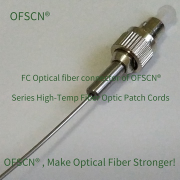
OFSCN® 300℃ Fiber Optic Connector: Supports PC and APC precision polishing (including FC, ST, SMA905 specifications). While ensuring excellent return loss metrics, it can operate stably in environments up to 300\ ^\circ\text{C} .
-
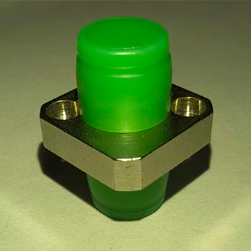
OFSCN® High Temperature Resistant Fiber Optic Adapter: Supports FC/APC-FC/APC type connections. The ceramic ferrule ensures precise positioning, guaranteeing extremely low additional insertion loss and return loss fluctuations, with a temperature resistance of up to 300\ ^\circ\text{C} .