Without unplugging the connector, how can I tell which jumper wire is carrying a signal?
Without disconnecting the fiber optic connector and interrupting communication services, identifying which patch cord is transmitting a signal and its transmission direction typically requires a specialized portable test instrument called an Optical Fiber Identifier (OFI).
The underlying physical principles, working mechanisms, and application limitations are as follows:
1. Core Physical Principle: Bending Loss & Macro-bending Leakage
When light travels through an optical fiber, it is perfectly confined within the core due to the principle of Total Internal Reflection. However, if the fiber undergoes a localized physical bend, the angle of incidence of the light at the core-cladding interface changes:
- When the bending radius decreases to a certain extent, the angle of incidence for some of the transmitted light at the interface becomes less than the critical angle for total internal reflection.
- At this point, this portion of the light no longer undergoes total internal reflection but refracts and leaks into the cladding and coating.
- The weak leaked optical energy penetrates the translucent fiber coating, tight buffer, and the outer jacket of the patch cord (typically a yellow single-mode 2.0\ \text{mm} or 3.0\ \text{mm} jacket), dissipating into the external environment.
2. Working Mechanism of an Optical Fiber Identifier
An optical fiber identifier is designed based on this principle:
- Applying a Safe Macro-bend:The patch cord to be tested is inserted into the identifier’s clamp (bending test chuck). Upon pressing the activation button, the clamp applies a small, controlled physical bend to the patch cord (the bending radius is strictly designed to produce a loss typically between 0.5\ \text{dB} and 1.5\ \text{dB}, which is sufficient to generate detectable leakage without damaging the fiber or interrupting the carried service).
- High-Sensitivity Photodetection:High-sensitivity photodetectors (usually InGaAs PIN detectors) are embedded on both sides of the bending point. The weak leaked optical signal (generally in the range of -30\ \text{dBm} to -40\ \text{dBm}) is captured by the detectors.
- Status and Direction Determination:
- Signal Presence (Traffic):If the detected optical power exceeds background noise, it indicates that an optical signal is being transmitted within the patch cord.
- Transmission Direction (Direction):Due to slight asymmetry in the spatial distribution of light leakage on both sides of the bending point, the instrument can accurately indicate whether the optical signal is transmitting from left to right or right to left by comparing the difference in light intensity received by the detectors on each side.
- Specific Frequency Modulation Signal (Tone Detection):In optical network maintenance, if a specific modulated light source (such as 270\ \text{Hz}, 1\ \text{kHz}, or 2\ \text{kHz}) is injected from the far end, the identifier can decode it and emit a corresponding beep, helping technicians precisely locate the fiber.
3. Application Limitations and Precautions
- Fiber Bend Sensitivity:Ordinary single-mode fibers (e.g., G.652D specification) exhibit noticeable light leakage when using an optical fiber identifier, making them easy to identify. However, for ultra-bend-insensitive fibers (e.g., G.657.B3), whose micro-bend and macro-bend losses are significantly suppressed by their physical structure, conventional optical fiber identifiers may fail to detect them due to extremely weak leakage. In such cases, higher sensitivity identifiers or advanced identifiers specifically optimized for G.657 fibers are required.
- Outer Jacket Limitations:This method is applicable to tight-buffered fibers or single-core patch cords with translucent or light-permeable outer jackets. If the fiber is encased in an opaque metallic armor, stainless steel tube, or a thick black outer jacket (such as some outdoor cables), the leaked light cannot penetrate the jacket, rendering this method inapplicable.
Technical Disclaimer:
Optical Fiber Identifiers (OFIs) are common tools for optical communication construction, link maintenance, and troubleshooting. They do not belong to the core product portfolio of Beijing Dacheng Yongsheng Technology Co., Ltd. (OFSCN®).
As a professional provider of specialty optical fibers and fiber sensing solutions, Beijing Dacheng Yongsheng Technology Co., Ltd. (OFSCN®) is dedicated to the research and production of:
- Specialty High-Temperature Optical Fibers (e.g., polyimide fibers with temperature resistance up to 300\ \text{℃}, and gold-coated fibers with temperature resistance up to 700\ \text{℃})
- Specialty Fiber Optic Sensors (e.g., Fiber Bragg Grating (FBG) sensors)
- Optical Demodulation Test Instruments (e.g., high-speed, high-precision fiber optic grating demodulators)
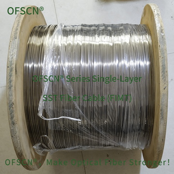
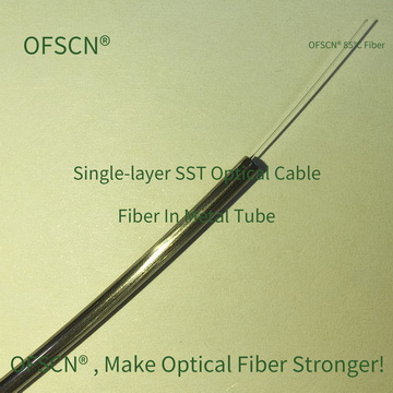
If your test object involves sensor cables encapsulated in specialty metal jacketing (e.g., OFSCN® 85°C Seamless Steel Tube Fiber Cable and similar seamless steel tube fiber optic cables), the absolute opacity and high mechanical rigidity of stainless steel and other metal tubes prevent the use of conventional bending fiber optic identifiers for non-destructive signal detection.
Product images are shown below: