Will the interrogator report an error because it “cannot see” clearly due to a long link or too many connectors?
Yes, if the link is too long or has too many connectors, the interrogator may indeed struggle to “see” the wavelength due to excessive optical power loss and insufficient signal-to-noise ratio, leading to lost peaks, inability to lock onto peak values, or errors.
In fiber optic sensing engineering, to prevent this issue, an Optical Power Budget assessment must be conducted during the system design phase.
I. What is “Optical Power Budget”?
Optical Power Budget refers to: the maximum allowable total optical loss in the system, from the optical power output by the interrogator (transmitter light source) to the minimum optical power required for the interrogator’s detector to stably and accurately identify spectral peaks (receive sensitivity).
Its general calculation formula is:
\text{Power Budget (dB)} = P_{\text{tx}} - P_{\text{rx\_min}}
- P_{\text{tx}} : Transmit optical power of the internal light source of the interrogator (Unit: \text{dBm} ).
- P_{\text{rx\_min}} : Minimum receive sensitivity threshold of the internal photodetector module of the interrogator (Unit: \text{dBm} ).
Physical Meaning: The total loss of the entire transmission link (including fiber transmission attenuation, loss from all active connectors, splice loss, splitter loss, and a safety margin) must be strictly less than the optical power budget.
II. Loss Components in FBG Reflective Sensing Links
Unlike ordinary unidirectional optical communication, Fiber Bragg Grating (FBG) sensing systems mostly adopt reflective measurement, requiring the optical signal to undergo a round-trip process: “transmission \rightarrow transmission \rightarrow sensor reflection \rightarrow return to interrogator”. The total link attenuation formula is:
\alpha_{\text{total}} = 2 \times (\alpha_{\text{fiber}} \cdot L) + 2 \times \sum \alpha_{\text{connector}} + 2 \times \sum \alpha_{\text{splice}} + \alpha_{\text{sensor}} + M
- Fiber Transmission Loss ( \alpha_{\text{fiber}} \cdot L ):
In the conventional 1550\ \text{nm} band (e.g., standard G.652D single-mode fiber), the transmission attenuation is approximately 0.2\ \text{dB/km}. Round-trip transmission loss is 0.4\ \text{dB/km} (round-trip loss for a 10\ \text{km} link is approximately 4\ \text{dB}). - Connector/Ferrule Loss ( \alpha_{\text{connector}} ):
The standard insertion loss for each fiber optic active connector (e.g., FC/APC, LC/APC) is typically 0.2\text{--}0.5\ \text{dB}. If the connector end face is contaminated, worn, or not properly tightened, the loss at a single point can surge to several \text{dB}. - Splice Loss ( \alpha_{\text{splice}} ):
High-quality fiber optic splices generally have a loss of 0.01\text{--}0.05\ \text{dB} per splice point. - Sensor Reflection Loss ( \alpha_{\text{sensor}} ):
This depends on the reflectivity of the Fiber Bragg Grating itself (conventional FBG reflectivity is around 70\%, resulting in an inherent reflection loss of about 1.55\ \text{dB}; using gratings with lower reflectivity in an array will result in greater single-point reflection loss). - Engineering Safety Margin ( M ):
An engineering design typically includes a 3\text{--}5\ \text{dB} safety margin for aging, bending stress, and minor end-face contamination.
III. Interrogator Phenomena Caused by Excessive Link Attenuation
When the link attenuation exceeds the optical power budget, the interrogator will exhibit the following physical phenomena:
- Peak Identification Failure (Peak Drop): The reflected signal peak is submerged in the optical baseline noise, and the signal-to-noise ratio (SNR) falls below the algorithm’s recognition threshold, causing the channel to display “No Sensor” or “No Reflective Wavelength.”
- Data Jitter/Increased Measurement Noise: Due to extremely weak light intensity, the wavelength fitting algorithm is severely affected by noise, resulting in significant random fluctuations in the measured temperature/strain data.
- “Lost Signal” for Subsequent Multiplexed Channels: When multiple FBGs are connected in series on a single fiber, sensors located further down the link receive weaker return signals and lose signal first.
IV. Official Hardware Support
When undertaking long-distance distributed monitoring or large-scale measurement point networking, it is advisable to select fiber Bragg grating interrogator equipment with high dynamic range and high resolution.
OFSCN® Fiber Bragg Grating Interrogator
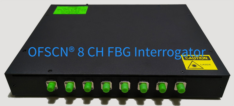
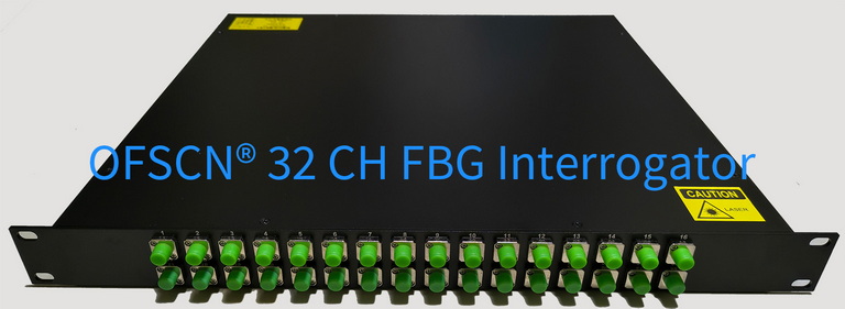
- Main Wavelength Range: Standard configuration is 1525\text{--}1565\ \text{nm} or 1528\text{--}1568\ \text{nm} (custom broadband options available).
- Channel Configuration: Supports 4, 8, 16, or 32 channels.
- Wavelength Resolution: Default is 1\ \text{pm}, with high-precision versions reaching 0.1\ \text{pm}.