1/99 or 10/90 are used in what special scenarios?
In the fields of optical fiber communication and distributed optical fiber sensing, “Unbalanced Splitters/Couplers”, especially those with splitting ratios of 1/99 (also known as 99:1) or 10/90 (also known as 90:10), belong to extremely asymmetric passive optical devices (typically manufactured using the Fused Biconical Taper, FBT, process).
These unbalanced splitters play an irreplaceable role in the following special engineering and academic scenarios:
1. Online Power Monitoring / Tap
This is the most classic application scenario for 1/99 splitters.
- Physical Mechanism: In high-power fiber lasers, Erbium-Doped Fiber Amplifiers (EDFAs), or backbone optical transmitters, it is necessary to monitor the current output optical power in real-time. Using a balanced splitter would cause severe loss of signal light intensity.
- Solution: Introduce a 1/99 splitter.
- Main Channel ( 99\% Port): Allows the signal light to pass with almost no loss, introducing a theoretical additional insertion loss of only about 0.04\text{ dB} , ensuring downstream transmission quality.
- Monitoring Channel ( 1\% Port): Guides an extremely weak optical power (attenuation of about -20\text{ dB} ) to a high-sensitivity photodetector (PD) for online monitoring of light source lifespan, changes in line attenuation, or as a control signal for a feedback loop.
2. Long-Distance Bus / Linear Topology
In communication or sensing networks distributed linearly along routes such as highways, tunnels, subways, and utility tunnels, a daisy-chain cascaded topology is often used to save backbone optical cables.
- Physical Mechanism: If only 50/50 balanced splitters are used, the optical power will decay exponentially and rapidly after cascading (after 5 stages of cascading, the optical power at the end will be attenuated to about 3\% of the original).
- Solution: Use unequal ratio splitters for “optical power equalization design”.
- Nodes at the front end, close to the light source, have extremely high light intensity and use 1/99 or 2/98 splitters, drawing only a small amount of energy for local use.
- Intermediate nodes sequentially use 5/95 , 10/90 , and 20/80 splitters.
- The very last nodes use 50/50 splitters.
- This cascading method can ensure that the absolute optical power received by each terminal node along the entire chain is approximately the same.
3. In-service Testing / OTDR Without Service Interruption
- Physical Mechanism: For backbone optical fiber links transmitting core business, communication cannot be interrupted for testing.
- Solution: Utilize 10/90 or 1/99 splitters, leaving 90\% or 99\% of the bandwidth and power for the main business traffic. The remaining small proportion port serves as a bypass, connecting to an Optical Time Domain Reflectometer (OTDR) or Optical Spectrum Analyzer (OSA). Without interfering with normal communication, a weak test light is injected or spectral analysis is performed to achieve real-time online fault diagnosis of the link status.
4. Fiber Interferometers and High Dynamic Range Sensor Networks (Interferometry & Sensor Balancing)
- Physical Mechanism: In fiber interferometers such as Michelson or Mach-Zehnder, the echo light intensity of the Reference Arm and the Sensing Arm needs to be similar to obtain interference fringes with maximum contrast.
- Solution: Since the Sensing Arm may penetrate harsh environments or undergo long-distance transmission, it faces much higher macro-bending, micro-bending, and scattering losses than the Reference Arm. Designers often use 10/90 or even more extreme asymmetric splitters, injecting 90\% of the power into the heavily attenuated Sensing Arm and 10\% into the Reference Arm, thereby achieving a perfect balance of echo power from both arms at the receiver and improving the system’s signal-to-noise ratio.
Relation to Beijing Dacheng Yongsheng Technology Co., Ltd. (OFSCN®) Products and Systems
In Beijing Dacheng Yongsheng Technology Co., Ltd.'s (OFSCN®) distributed Fiber Bragg Grating (FBG) temperature and strain sensing networks, precise optical power budgeting and channel management are crucial.
To effectively expand the physical channels of FBG demodulators and reduce the hardware cost per measurement point, high-quality optical splitters (such as typical 1x2 and 1x4 balanced splitters, using strict wavelength planning to multiplex FBG sensors in different channels) are usually used on the main transmission lines.
However, when facing complex long-distance pipeline sensing or large-scale hybrid (star + chain) FBG sensing network construction in multi-story high spaces, unbalanced splitters (such as 10/90 ) can serve as core components for optical energy fine-tuning, ensuring that the grating spectral reflection received by each sensing channel in the entire network reaches the optimal demodulation threshold.
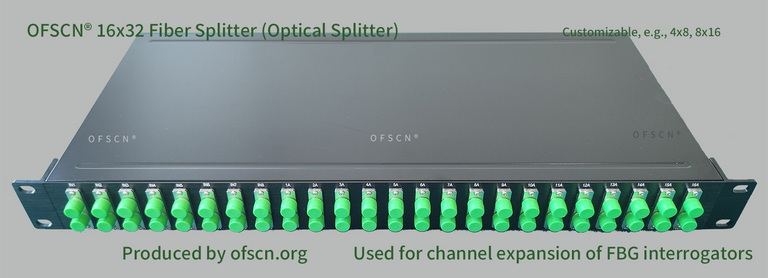
For cascading wavelength planning and link loss budget engineering indicators of such optical devices in FBG sensing networks, please refer to the official product page:
OFSCN® Optical Fiber Splitter