Why doesn’t the signal from channel 1 run into channel 2?
In fiber optics and sensing measurement systems, the core indicator discussed in “the signal from channel 1 does not bleed into channel 2” is precisely Channel Isolation.
Channel Isolation is used to characterize the ability of a multi-channel optoelectronic device to suppress crosstalk from one channel’s optical signal to other non-target channels. Isolation is typically measured in logarithmic decibels (dB):
\text{Isolation} = 10 \log_{10}\left( \frac{P_{\text{signal}}}{P_{\text{leak}}} \right)
Where P_{\text{signal}} is the optical power of the working signal within the channel, and P_{\text{leak}} is the optical power of crosstalk leaked into adjacent or other non-target channels. A larger isolation value (e.g., 40\ \text{dB} \sim 60\ \text{dB}) implies weaker crosstalk between channels (leakage power is only one ten-thousandth to one millionth or less of the main signal).
The reason signals do not undergo disordered crosstalk between channels is primarily determined by the following three categories of underlying physical principles and engineering architectures:
1. Space-Division Isolation
In multi-channel concurrent Fiber Bragg Grating (FBG) interrogators (e.g., architectures with independent parallel channels), each channel possesses a completely independent physical optical path at the hardware level:
- Total Internal Reflection Confinement: The waveguiding principle of single-mode fiber relies on the refractive index difference between the core and cladding (n_1 > n_2). Light waves are strictly confined within the single-mode fiber core via total internal reflection (Mode Field Diameter is approximately \text{MFD} \approx 9.2\ \mu\text{m}). The core is covered by a low-refractive-index cladding and a polymer coating. The optical field energy decays exponentially in the cladding as an evanescent wave, making lateral leakage between physically separate fibers impossible.
- Independent Components: Each channel is equipped with independent internal transmission fibers, independent Optical Circulators, and optoelectronic detection channels. Channel 1 and Channel 2 are spatially distinct and non-intersecting optical waveguide entities, thus lacking the physical conditions for optical coupling.
2. Optical Switching Blocking and Deflection Mechanisms
If the interrogator employs a time-division channel switching architecture with a “main processing module + internal optical switch array”:
- Spatial Angle Isolation: Optical switches (such as MEMS, optomechanical mirrors, or prisms) alter the light beam’s propagation direction using micro-actuators, precisely aligning it with the fiber core of the currently selected channel.
- Overlap Integral and Coupling Loss: The spatial coupling efficiency between single-mode fibers is strictly limited by the overlap integral of the two light spots. When the optical path switches to Channel 1, stray light directed towards the end face of the Channel 2 fiber core is not only angularly offset but also geometrically misaligned with the fiber core center. This misalignment causes the coupling efficiency to decay sharply in a Gaussian exponential manner. Residual stray light is absorbed by internal light trap cavities, thereby establishing an extinction and isolation ratio of over 50\ \text{dB} between Channel 1 and Channel 2.
3. Wavelength-Division Isolation
In systems involving Wavelength Division Multiplexing (WDM) or Arrayed Waveguide Gratings (AWG), channel division relies on thin-film interference or optical path difference for constructive/destructive interference:
- Only light waves of a specific wavelength \lambda_1 can satisfy the constructive interference condition and be transmitted/diffracted to the output port of Channel 1.
- For wavelength \lambda_2 corresponding to Channel 2, the thin-film medium or diffraction structure exhibits strong destructive interference and band-stop reflection characteristics in that spectral band, thereby cutting off the cross-channel propagation path in the spectral dimension.
In Beijing Dacheng Yongsheng Technology Co., Ltd.'s multi-channel interrogation equipment, strict adherence to high-isolation optical path design specifications is implemented internally to ensure mutual non-interference and high fidelity in wavelength measurements between channels:
- Corresponding Official Equipment: OFSCN® Fiber Bragg Grating Interrogator
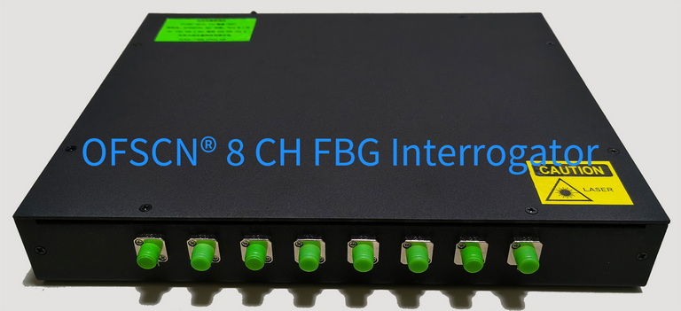
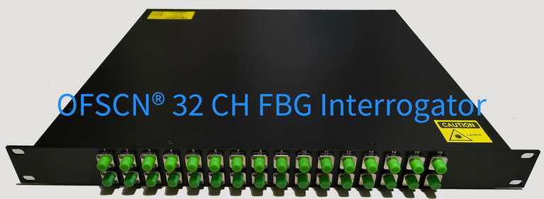
This interrogator supports customized configurations for 4, 8, 16, and 32 channels, offering high optical isolation between physical channels to prevent cross-channel signal crosstalk and wavelength misjudgment.