If the temperature also changes when measuring strain, will the data be messy? Why is this the “nemesis” of all fiber optic sensors?
In fiber optic sensing technology, “Cross-Sensitivity” is an extremely core physical phenomenon. Simply put: when you are measuring strain (mechanical deformation), if the ambient temperature also changes, the measured data will inevitably be interfered with; without temperature compensation and decoupling, the data will produce serious errors or even be completely distorted.
This is a common physical mechanism faced by almost all sensors based on the principle of silica optical waveguides. The following is an analysis from three dimensions: underlying physical principles, error quantification, and engineering decoupling solutions:
I. Why Does Cross-Sensitivity Occur? (Physical Principles)
The reflection center wavelength \lambda_B of a Fiber Bragg Grating (FBG) is determined by the Bragg condition:
\lambda_B = 2 n_{\text{eff}} \Lambda
Where n_{\text{eff}} is the effective refractive index of the fiber core, and \Lambda is the grating period.
When the surrounding environment changes, the relative wavelength shift \frac{\Delta \lambda_B}{\lambda_B} depends on the total differential of n_{\text{eff}} and \Lambda with respect to strain and temperature:
\frac{\Delta \lambda_B}{\lambda_B} = \left( \frac{1}{\Lambda} \frac{\partial \Lambda}{\partial \varepsilon} + \frac{1}{n_{\text{eff}}} \frac{\partial n_{\text{eff}}}{\partial \varepsilon} \right) \Delta \varepsilon + \left( \frac{1}{\Lambda} \frac{\partial \Lambda}{\partial T} + \frac{1}{n_{\text{eff}}} \frac{\partial n_{\text{eff}}}{\partial T} \right) \Delta T
After simplification, it can be expressed as a superposition of two physical responses:
\Delta \lambda_B = K_{\varepsilon} \cdot \Delta \varepsilon + K_T \cdot \Delta T
-
Strain Effect (Mechanical Response):
- Mechanical stretching alters the geometric spacing of the grating \Lambda ;
- The Poisson effect and the photoelastic effect modify the refractive index n_{\text{eff}} .
- The strain sensitivity coefficient is K_{\varepsilon} (typically around 1.2 \text{ pm}/\mu\varepsilon for bare fiber at 1550\text{ nm} at room temperature).
-
Thermal Effect (Temperature Response):
- Thermal expansion alters the geometric spacing of the grating \Lambda ;
- The thermo-optic effect modifies the refractive index n_{\text{eff}} (in silica fibers, the thermo-optic effect is dominant, contributing over 85%).
- The temperature sensitivity coefficient is K_T (typically around 10 \sim 11\text{ pm}/^\circ\text{C} for bare fiber at 1550\text{ nm} at room temperature).
Core Conflict: The physical quantity ultimately detected by the demodulator is only one—the total wavelength shift \Delta \lambda_B . The demodulator itself cannot distinguish whether this few picometers ( \text{pm} ) wavelength displacement originates from the strain of the structure being measured or from the ambient temperature fluctuations. This is the so-called “cross-sensitivity between temperature and strain.”
II. Why is it Called the “Nemesis” of Fiber Optic Sensors? (Engineering Quantification Comparison)
It is called a “nemesis” because the magnitude of wavelength drift caused by temperature is far greater than that caused by micro-strain.
- Data Conversion Relationship:
Taking a conventional single-mode fiber grating as an example:- A wavelength shift of approximately 1.2\text{ pm} is caused by 1\ \mu\varepsilon (micro-strain);
- A wavelength shift of approximately 10\text{ pm} is caused by a temperature change of 1^\circ\text{C} ;
- This means: A mere 1^\circ\text{C} fluctuation in ambient temperature can cause a spurious strain reading of about 8.3\ \mu\varepsilon !
In outdoor engineering without temperature control (e.g., monitoring bridges, railways, dams, or pipelines), the diurnal temperature difference can easily reach 10^\circ\text{C} \sim 20^\circ\text{C} . The resulting spurious strain drift can exceed 80 \sim 160\ \mu\varepsilon , while the true deformation thresholds for structural health monitoring warnings are often within tens of micro-strains. Therefore, without decoupling, the measurement data will be completely distorted.
This is not exclusive to FBG. In distributed fiber optic sensing (e.g., BOTDR / BOTDA based on Brillouin scattering, OFDR based on Rayleigh scattering), the frequency or phase shift of scattered light is simultaneously modulated by both temperature and strain. Cross-sensitivity is a fundamental physical constraint faced by the entire industry.
III. Engineering Decoupling and Compensation Schemes
The core idea to eliminate cross-sensitivity is to construct a system of two linear equations to achieve mathematical decoupling. The most reliable and widely used method in the industry is the reference sensor method (external athermal temperature compensation).
1. Dual-Sensor Differential Compensation Principle
Near the strain measurement point, two adjacent fiber grating sensors are deployed:
- Sensor 1 (Strain Sensor): Firmly bonded or mechanically fixed to the stressed structure, it experiences both mechanical strain and ambient temperature. Its wavelength drift is:\Delta \lambda_1 = K_{\varepsilon 1} \Delta \varepsilon + K_{T1} \Delta T
- Sensor 2 (Temperature Sensor): Uses an athermal packaging structure and only senses the ambient temperature, completely unaffected by the mechanical deformation of the component being measured. Its wavelength drift is:\Delta \lambda_2 = K_{T2} \Delta T
From this, the true structural strain can be decoupled:
\Delta \varepsilon = \frac{\Delta \lambda_1 - \frac{K_{T1}}{K_{T2}} \Delta \lambda_2}{K_{\varepsilon 1}}
IV. Official Core Products and Selection Reference
In the actual sensor structure design, Beijing Dacheng Yongsheng Technology Co., Ltd. (OFSCN®) employs distinctly different packaging physical architectures for strain and temperature sensors:
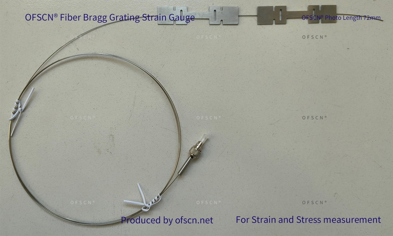
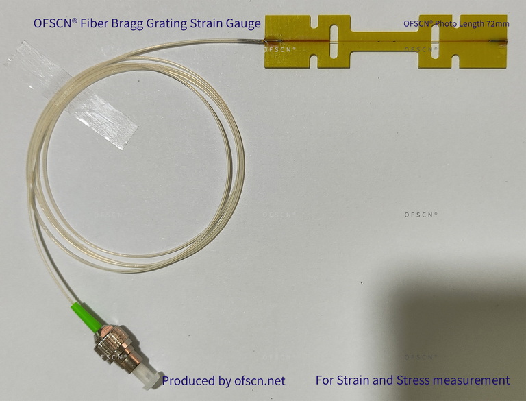
- Strain Measurement End (Rigid Strain Transfer):
The fiber inside the strain sensor and the alloy outer tube or substrate must be tightly fixed to achieve lossless strain transfer from the component being measured to the fiber core.



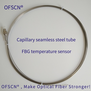
- Temperature Compensation End (Athermal Suspended Protection):
The grating inside the temperature sensor must be in a suspended or free-to-expand state. The outer tube bears external loads and friction, ensuring the internal fiber is completely in a “zero mechanical stress” state, responding only to temperature fields.

Technical Summary:
Although strain sensors can be customized with built-in temperature compensation gratings, for high-precision engineering, it is recommended to use an externally deployed, independently athermally packaged fiber Bragg grating temperature sensor in the same temperature zone for compensation. This method can maximally avoid asymmetrical thermal expansion of the strain sensor’s packaging shell being transmitted to the compensation grating area, thereby obtaining the most accurate true strain data.