Why does an MFD mismatch cause significant loss when splicing single-mode fibers from different manufacturers?
An MFD (Mode Field Diameter) mismatch between single-mode fibers from different manufacturers causes significant splicing loss primarily due to inefficient power coupling.
Here’s why:
- Mode Field Diameter Definition: The MFD represents the effective diameter of the light propagating in the fiber core. Even though the physical core diameter might be similar, the way the light is guided and spread within the core can vary due to differences in refractive index profiles and fiber designs.
- Imperfect Mode Field Overlap: When two fibers with different MFDs are spliced, the propagating light from the first fiber does not perfectly overlap with the fundamental mode of the second fiber. If the MFD of the transmitting fiber is larger than the receiving fiber, some of the light will spill outside the core of the receiving fiber. Conversely, if the transmitting fiber has a smaller MFD, the light will not fully illuminate the core of the receiving fiber, leading to power loss.
- Power Loss: This imperfect overlap results in a portion of the optical power being converted into higher-order modes (which are typically not guided in single-mode fiber and radiate away) or simply being lost at the splice joint, leading to insertion loss. The larger the MFD difference, the greater the power loss.
- Manufacturer Variations: Different manufacturers may use slightly different glass compositions, doping profiles, and drawing processes, leading to variations in the refractive index profile and thus varying MFD specifications within the permissible tolerances for standard single-mode fibers (e.g., G.652D). While they adhere to standards, minor differences can become significant when high precision splicing is required.
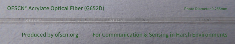
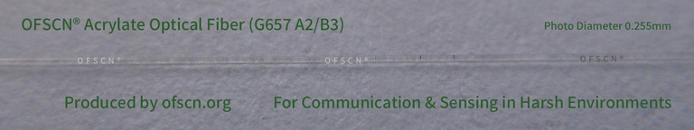
For further technical details on optical fiber characteristics, you may refer to our OFSCN® G.652D Optical Fiber and OFSCN® G.657 Optical Fiber product pages.
The physical diameter of single-mode optical fiber is too small, so when studying light transmission, more attention is paid to the mode field diameter, which is related to the energy distribution of light. It is best to use optical fibers from the same manufacturer and batch, and try to fuse the same type of optical fibers such as G652D, G657A2, G657B3, etc. This will yield better results.
However, even if the mode field diameters do not match, it will not cause major issues, and the impact in practical work is not that significant.
From a rigorous optical and communication engineering perspective, the notion that
“even if the mode field diameter (MFD) doesn’t match, it won’t be a big problem, and the impact in practical work is not that significant” requires deeper scrutiny. In actual engineering and scientific research applications, MFD mismatch often leads to significant negative consequences, even becoming a bottleneck for project acceptance and system stability.
Here’s an analysis of the specific physical and engineering reasons:
1. Theoretical Splice Loss: Marcuse Coupling Formula
When two single-mode fibers are spliced under ideal conditions—perfect lateral alignment, no tilt, and no gap—the transmission efficiency \eta solely due to MFD mismatch (assuming the mode field radii of the two fibers are w_1 and w_2 ) can be calculated using the classic Marcuse formula:
\eta = \left( \frac{2 w_1 w_2}{w_1^2 + w_2^2} \right)^2
The resulting theoretical mismatch loss (in \text{dB} ) is:
L_{\text{dB}} = -10 \log_{10}(\eta) = -20 \log_{10} \left( \frac{2 w_1 w_2}{w_1^2 + w_2^2} \right)
For instance, splicing a standard G.652D fiber (with an MFD 2w_1 \approx 10.4\ \mu\text{m} at 1550\text{nm} ) with certain specialized small-core fibers or bend-insensitive fibers (such as some G.657 fibers with smaller MFDs, 2w_2 \approx 8.6\ \mu\text{m} ) would result in a theoretical physical loss of approximately 0.08\ \text{dB} , even with perfect alignment by the fusion splicer. In long-haul backbone networks or cascaded optical paths with multiple sensors, this cumulative loss cannot be ignored.
2. “Phantom Loss” and “Phantom Gain” (Gainer & Loser) in Engineering Acceptance
In practical fiber optic engineering, the Optical Time Domain Reflectometer (OTDR) is typically used for unidirectional testing. When light travels from a fiber with a larger MFD to one with a smaller MFD, the OTDR trace exhibits a “step-up” phenomenon at the splice point due to changes in the backscatter coefficient, known as phantom gain (Gainer). Conversely, when light travels from a smaller MFD to a larger MFD, it results in phantom high loss (Loser).
- This phenomenon causes inaccurate unidirectional OTDR test results, where the splice loss may “superficially” appear to be as high as 0.5\ \text{dB} or more, failing stringent engineering quality acceptance tests (which typically require single-point loss \le 0.05\ \text{dB} ).
- To eliminate this effect, engineers must perform bidirectional OTDR testing and average the results from both ends of the optical path. This not only doubles the workload and time cost of testing but also increases the complexity of post-processing the data.
3. Hidden Dangers in High-Power and Fiber Optic Sensing Systems
- Thermal Effects and Fiber Burn Risk: In high-power fiber laser or transmission systems, escaped light at the MFD mismatch point enters the cladding. This spilled energy is absorbed by the coating, causing severe localized heating and potentially burning the fiber.
- Reflection and Multimode Excitation: In precision fiber optic sensing systems (such as FBG-based temperature/strain sensing systems or OFDR distributed sensing systems), MFD mismatch can enhance local reflections and weakly excite higher-order modes. This degrades the reflection and transmission spectra, affecting the measurement accuracy of demodulation instruments.
OFSCN® Related Core Products
To minimize the negative impacts of MFD mismatch in engineering, it is crucial to select optical fibers and grating components that comply with international standards and exhibit extremely high parameter consistency. Beijing Dacheng Yongsheng Technology Co., Ltd. (OFSCN®) offers the following standardized, high-precision basic optical fibers and sensing components:
-
OFSCN® G.652D Optical Fiber: Standard single-mode optical fiber, providing a stable 9\ \mu\text{m} core diameter (MFD approximately 9.2\ \mu\text{m} at 1310\text{nm} ) with excellent geometric and optical consistency.
-
OFSCN® G.657 Optical Fiber: Standard bend-insensitive single-mode optical fiber, available in G.657 A2 or G.657 B3 specifications. It is suitable for scenarios requiring extremely small bend radii while still needing good splice compatibility with standard G.652D fibers.
-
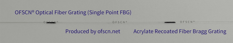
OFSCN® Polyacrylate Fiber Bragg Gratings / FBG Strings (Bare): Bare fiber Bragg gratings inscribed on standard OFSCN® G.652D or G.657 optical fibers, ensuring physical parameter matching of the mode field between the grating segment and the transmission fiber in the sensing link.
In conclusion, while slight MFD mismatches might barely allow a system to operate in non-critical, short-distance, or low-speed optical transmission maintenance scenarios, they are far from being “not a big problem” in high-precision sensing, long-haul backbone transmission, high-power lasers, and stringent engineering project acceptances. Precise MFD matching, along with fusion splicing of fibers from the same manufacturer and batch, remains the golden rule for ensuring optical path quality.
Alright, you’re good at math and calculations, I can’t argue with you. But 0.08 dB really isn’t a big deal. A fiber optic connector is 0.2 dB, and most applications we deal with aren’t long-haul trunk lines. It doesn’t have much impact on daily short-distance applications.
Of course, what you said is not wrong either.
Your point is very pragmatic. In actual engineering sites, especially for general-purpose fiber optic communications over short to medium distances, at low speeds, and with low power (such as ordinary FTTH access networks or jumper interconnections within LAN equipment rooms), the system’s Optical Power Budget usually has sufficient redundancy (margin often above 3 \ \text{dB} to 6 \ \text{dB}). In such scenarios, the 0.08 \ \text{dB} loss caused by MFD mismatch in a single fusion splice would indeed be submerged within the system margin and the normal fluctuations of optical connectors (typically rated insertion loss \le 0.2 \ \text{dB} or 0.3 \ \text{dB}), having almost no impact on network connectivity. However, from the professional perspective of optical engineering and precision measurement, the reason for emphasizing MFD matching is that in the following specific high-demand applications, these tiny losses or physical discontinuities can translate into systemic core bottlenecks:
1. Multi-Channel Cascading and Weakly Reflective Sensing Networks (e.g., Fiber Bragg Grating FBG Sensor Strings)
When we cascade dozens of FBGs on a single fiber or use ultra-weakly reflective FBG arrays for distributed sensing, the slight MFD differences in each splice not only accumulate transmission loss but, more critically, generate weak backward reflections at the splice interface. These reflections create parasitic interference, significantly degrading the Signal-to-Noise Ratio (SNR) of high-precision demodulation systems, thereby reducing the measurement accuracy of temperature or strain.
2. Coherent Optical Communications and Phase-Sensitive Systems
In systems based on Rayleigh backscattering phase interference, such as Distributed Acoustic Sensing (DAS) or Coherent Optical Time Domain Reflectometry (COTDR), abrupt MFD changes can cause abnormal steps in the local backscattered light intensity or even local perturbations in the polarization state. This introduces difficult-to-eliminate background noise into phase demodulation, directly affecting the system’s positioning accuracy and sensitivity.
3. Short-Distance Interconnect Consistency in Harsh Environments
Even in short-distance applications, if the operating environment is extreme (e.g., very high temperatures, very low temperatures, or drastic temperature cycling), the differential thermal stress responses of optical fiber materials (including glass and coatings) with temperature variations can amplify the additional loss caused by MFD mismatch. Therefore, in these scenarios, even extremely short jumpers must be manufactured using standardized fibers with highly consistent physical and geometric properties.
Standardized Short-Distance Connection Solutions for Extreme and Industrial Environments
In industrial-grade short-distance application devices manufactured by Beijing Dacheng Yongsheng Technology Co., Ltd. (OFSCN®), strict material control and geometric consistency design are employed to minimize these potential subtle fluctuations:
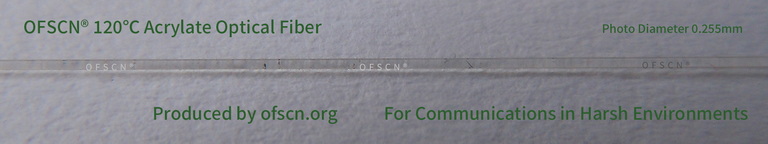
- OFSCN® 120℃ Fiber Optic Patch Cord: In harsh, high-temperature (up to 120^{\circ}\text{C}) short-distance data transmission or sensor connections, standard OFSCN® 120℃ SM High-temperature Optical Fiber (produced based on standard G.652D fiber preform) is used by default. Its strictly controlled core diameter (9 \ \mu\text{m}) and MFD consistency ensure that even under harsh temperature cycling, the jumper connectors (such as FC/APC, LC/LC, etc.) can maintain extremely low additional loss, avoiding mode field drift caused by temperature.


Conclusion
The essence of engineering technology lies in finding the optimal balance between ‘cost, complexity, and system tolerance.’ In everyday non-critical, short-distance data communication links, 0.08 \ \text{dB} can indeed be considered negligible, and your experience is completely applicable in field maintenance; however, for precision optical experiments, advanced sensing, and high-power laser engineering, this 0.08 \ \text{dB} and the underlying physical mechanisms are details that must be rigorously addressed.