How can a demodulator, sensors, and alarms be combined into a complete solution?
“Fiber Optic Sensing System Integration” refers to the process of constructing an engineering system capable of closed-loop monitoring and linkage by physically connecting, converting protocols, and employing software algorithms to integrate optical sensing elements, optoelectronic signal demodulation devices, data processing and computing units, and external industrial control/alarm execution devices.
In system engineering, combining fiber optic sensors, fiber Bragg grating interrogators, and alarms into a complete solution is typically divided into the following four levels and signal flow processes:
I. System Topology and Level Division
[ Field Under Test ] Fiber Bragg Grating Sensors (FBG Sensors)
                    │  (Fiber Optic Link / Optical Signal Transmission)
                    ▼
[ Data Acquisition ] Fiber Bragg Grating Interrogator (FBG Interrogator)
                    │  (Industrial Network: TCP/IP / UDP / Modbus)
                    ▼
[ Data Processing ] Edge Monitoring Host / Upper Computer Software (Algorithmic Determination and Threshold Analysis)
                    │  (Digital Output DO / Relay / Network Command)
                    ▼
[ Terminal Execution ] Audible and Visual Alarms / Linkage Control Mechanisms (PLC, Fire Protection, or Shutdown Circuits)
II. Specific Integration Steps and Implementation Principles
1. Sensing Layer: Sensor and Fiber Optic Circuit Deployment
- Physical Connection: Fiber Bragg Grating (FBG) sensors are connected in series or at single points to on-site monitoring locations via armored fiber optic patch cords (commonly using standard interfaces like FC/APC).
- Optical Response: Changes in external physical quantities (temperature T, strain \varepsilon, stress, etc.) cause alterations in the grating period \Lambda or the effective refractive index n_{eff}, leading to a linear drift in the reflected Bragg wavelength \lambda_B:\Delta \lambda_B = 2 (\Delta n_{eff} \Lambda + n_{eff} \Delta \Lambda)
2. Demodulation Layer: Optical-to-Digital Signal Conversion
- Optoelectronic Demodulation: The FBG interrogator transmits a broadband light source into the fiber optic circuit. An internal spectral analysis module detects the central wavelength \lambda_B reflected from each measurement point.
- Interrogator Communication Integration: The interrogator extracts spectral peaks and quantifies them into wavelength data. The demodulation device uploads the high-speed wavelength stream data to the processing host via standard communication protocols (such as TCP/IP, UDP, or the industrial standard Modbus protocol).
3. Processing Layer: Engineering Unit Conversion and Alarm Algorithm Logic
- Calibration Formula Calculation: The monitoring software utilizes the factory physical calibration coefficients of the sensor (e.g., sensitivity coefficients K_T\ (\text{pm}/^{\circ}\text{C}) or K_{\varepsilon}\ (\text{pm}/\mu\varepsilon) ) to convert the acquired wavelength in real-time into specific physical engineering units (such as temperature values, micro-strain values).
- Multi-dimensional Alarm Logic:
- Fixed Threshold Alarm: Measured value exceeds an absolute threshold (e.g., temperature > 80\ ^{\circ}\text{C}).
- Rate of Change Alarm (Temperature Rise Rate): The rate of change of the physical quantity over a unit of time is exceeded (e.g., dT/dt > 5\ ^{\circ}\text{C}/\text{min}).
- Difference Alarm: The difference between the same circuit or symmetrical measurement points exceeds a limit (e.g., \Delta T > 10\ ^{\circ}\text{C}).
4. Execution Layer: Alarm Output and Hardware Linkage
- Execution Trigger: When the system determines that alarm conditions are met, the upper computer or the interrogator’s extended I/O module closes the digital output interface (DO digital output / relay normally open or normally closed contacts).
- Alarm Driver: An external audible and visual alarm is activated by closing its power supply circuit, producing audible and flashing warnings. It can also be linked to fire protection systems, PLC control circuits, or accident cutoff devices via Modbus/Ethernet protocols.
III. Core Products and Integration Support
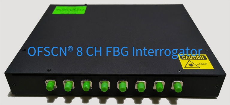
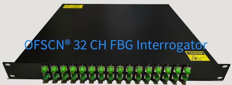
Within the fiber optic sensing integration chain, the fiber Bragg grating interrogator serves as a crucial central hub. Beijing Dacheng Yongsheng Technology Co., Ltd. offers demodulation equipment compatible with industrial integration protocols:
- OFSCN® Fiber Bragg Grating Interrogator: Available in configurations with 4, 8, 16, or 32 channels, offering wavelength resolution up to 1\ \text{pm} or 0.1\ \text{pm}. It supports B/S and C/S software architectures and provides standard TCP, UDP, and Modbus data interfaces, facilitating direct reading of raw or engineering data by system integrators via industrial networks.
(Note: Audible and visual alarms, relay modules, PLC control boxes, etc., in the system are general electrical/industrial control hardware and do not belong to the core product series of OFSCN® passive fiber optic sensors from Beijing Dacheng Yongsheng Technology Co., Ltd. In practical integration, third-party industrial actuators are typically selected and connected based on specific engineering standards and power supply voltages (e.g., DC 24V, AC 220V).)