Does a signal weaken when passing through a jumper connection? What is an acceptable loss?
When a light signal passes through a fiber optic patch cord connector or adapter, the signal is bound to weaken. This total reduction in optical power caused by the insertion of components such as connectors, patch cords, or ferrules into an optical transmission system is known in optical engineering as Insertion Loss (IL).
The formula for calculating it is:
IL = -10 \log_{10} \left( \frac{P_{\text{out}}}{P_{\text{in}}} \right) \quad (Unit: dB)
Where P_{\text{in}} is the input optical power and P_{\text{out}} is the output optical power after passing through the connector. The lower the value (absolute value) of insertion loss, the smaller the energy attenuation of the optical signal when passing through the connector.
I. Why Does the Signal Weaken? (Physical Principles and Causes of Loss)
When an optical signal passes through two aligned fiber optic plugs (connectors), attenuation is mainly caused by the following physical factors:
- Lateral Misalignment / Offset
This is the primary physical cause of insertion loss. If the fiber cores of two aligned connectors (the core diameter in single-mode fiber is only about 9\,\mu\text{m}) cannot be perfectly coaxial, and there is a slight radial offset in their axes, some optical power will leak into the cladding and rapidly attenuate. - Longitudinal Separation & Fresnel Reflection
If there is a small air gap between the two end faces instead of physical contact, light will undergo Fresnel Reflection when passing through the “glass-air-glass” interface due to the abrupt change in refractive index (glass n \approx 1.45, air n \approx 1.0). Each reflection causes a loss of about 0.15\,\text{dB} to 0.2\,\text{dB} and generates a backward echo. - Angular Misalignment
A slight angle between the axes of the two fibers causes incident light to not fully satisfy the condition of total internal reflection, leading to leakage from the fiber core. - End-face Quality & Contamination
If the contacting end faces have even tiny amounts of dust, grease, moisture, wear, or scratches, it will cause severe light scattering and light absorption. This is the most common reason for a sudden increase in insertion loss in practical engineering environments. - Fiber Geometric Inconsistency
If the two aligned fibers have inconsistent core diameters, numerical apertures (NA), or concentricity due to manufacturing tolerances, it will also cause intrinsic loss.
II. What is Considered Acceptable Loss?
Whether a connector meets quality standards is usually determined by two metrics: Insertion Loss (IL) and Return Loss (RL).
1. Insertion Loss (IL) Judgment Standard
- Industry-wide Maximum Upper Limit Standard (e.g., TIA/EIA-568-C.3 standards):
- The maximum allowable insertion loss for a single fiber optic connector is \le 0.75\,\text{dB}.
- Commercial and Industrial Grade Factory Acceptance Standard (Telecommunication-grade high-quality patch cords):
- Single-mode Fiber Connector (SM): The pass line usually requires \le 0.3\,\text{dB} per point (in precision assembly, typical values are usually between 0.1\,\text{dB} and 0.2\,\text{dB}).
- Multi-mode Fiber Connector (MM): The pass line is also usually \le 0.3\,\text{dB}.
- If the loss of a single patch cord connector exceeds 0.5\,\text{dB} during field testing, it is usually necessary to clean the end face again and re-test; if it still exceeds the limit, it indicates that the plug is off-center, the end face is damaged, or the assembly is not qualified, and it should be replaced.
2. Return Loss (RL) Judgment Standard (Measures the strength of reflected signals)
The higher the return loss value, the less interference light is reflected back to the light source, and the better the transmission quality:
- PC / UPC End-face (Physical Contact with spherical micro-convex): Standard requires \ge 50\,\text{dB}.
- APC End-face (Angled Physical Contact at 8^\circ): Due to its angled design that directs reflected light into the cladding, the standard requires \ge 60\,\text{dB}.
III. Precision Patch Cords and Connectors for Industrial and High-Precision Applications
In precision fiber optic sensing (e.g., fiber Bragg grating demodulation systems) or high-speed optical communication, to ensure extremely low insertion loss for long-term system operation, there are extremely high requirements for the mechanical precision and temperature resistance of patch cords and ferrules.
OFSCN® provides high-precision industrial-grade transmission accessories for different working conditions. They are precision-ground and rigorously tested before leaving the factory, ensuring excellent low insertion loss in various temperature and stress environments:
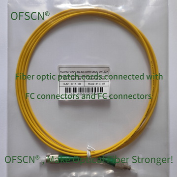
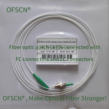
1. Standard Temperature and General Test Patch Cords
-
OFSCN® Standard Fiber Patch Cord: Standard fiber optic patch cord. Manufactured with precision zirconia ceramic ferrules, it ensures that the single-point insertion loss is strictly controlled at a low level, providing highly reproducible and stable connections.
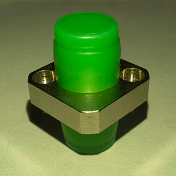
2. Special Patch Cords and Adapters for Extreme High-Temperature Environments
In field environments with drastic temperature changes (e.g., industrial environments up to 300^\circ\text{C}), if ordinary patch cords are used, the internal adhesive, jacket, and ferrule structure will undergo thermal expansion and softening, causing end-face misalignment and resulting in extremely large fluctuations in insertion loss. Therefore, specialized high-temperature resistant seamless steel tube protected patch cords and metal ferrules are required:
-
OFSCN® High Temperature Resistant Fiber Optic Adapter: High-temperature resistant fiber optic ferrule/adapter (withstands up to 300^\circ\text{C}), the precision alignment sleeve effectively prevents optical alignment drift caused by temperature changes, maintaining low-loss connections under extreme conditions.