Why does even subtle, invisible pressure cause light to “leak”?
Microbending Loss is a common and critical optical loss mechanism in fiber optics and sensing engineering. The ability of light waves to transmit over long distances with low loss in the fiber core relies on the condition of Total Internal Reflection (TIR) at the interface between the core (refractive index n_1) and the cladding (refractive index n_2, with n_1 > n_2).
Invisible micro-compressions cause light to “leak” out. The underlying physical mechanisms are primarily related to microscopic waveguide perturbations and mode energy conversion:
1. Micro-scale Geometric Deformation and Critical Angle Disruption
The core diameter of single-mode optical fibers is typically only about 9\ \mu\text{m} (about one-tenth the diameter of a human hair). When the fiber experiences subtle lateral compressions invisible to the naked eye (e.g., due to external rough particles, uneven coating shrinkage, or local hard contact), the fiber axis undergoes high-frequency, random micro-bends on the micrometer scale (\mu\text{m}-level).
- Local Tangent Angle Deflection: At microscopic convexities and concavities, the normal vector direction of the core-cladding interface is deflected.
- Disruption of Total Internal Reflection: Light rays that were originally propagating obliquely within the core at an angle greater than the critical angle \theta_c = \arcsin(n_2 / n_1) experience an instantaneous decrease in their angle of incidence when encountering local micro-inclinations of the interface. This angle drops below the critical angle \theta_c, causing the light to no longer undergo total internal reflection but instead to refract and “leak” into the cladding, eventually being absorbed and dissipated at the cladding-outer coating interface.
2. Wave Optics Explanation: Mode Coupling Theory
From the perspective of electromagnetic wave equations and mode theory, light propagating in optical fibers exists as discrete “guided modes”:
-
Spatial Perturbation Frequency Matching: The lateral pressure caused by microbends introduces periodic or quasi-periodic microscopic refractive index perturbations along the fiber axis. Let the spatial perturbation frequency be \Lambda.
-
Transition from Guided Modes to Radiation Modes: When the phase matching condition is met by the spatial propagation constant of the microbend perturbation:
\Delta \beta = \beta_{\text{core}} - \beta_{\text{clad}} \approx \frac{2\pi}{\Lambda}The energy of the core fundamental mode (LP_{01}) undergoes resonant coupling with cladding radiation modes. Guided mode energy is continuously pumped into radiation modes, causing light signals to be continuously radiated out of the cladding at a microscopic scale, which macroscopically manifests as significant light attenuation.
3. Photoelastic Effect
Local micro-compressions can induce highly concentrated shear stresses and non-uniform stress fields within the material. According to the photoelastic effect, the refractive index of silica glass undergoes anisotropic distortion (stress birefringence) when subjected to pressure, which disrupts the originally highly circularly symmetric refractive index profile. This creates microscopic refractive index step perturbations at the waveguide boundary, further accelerating the loss of guided mode energy into radiation modes.
4. Distinction Between Microbending and Macrobending
| Physical Characteristic | Macrobending | Microbending |
|---|---|---|
| Bending Scale | Visible to the naked eye (radius of curvature typically in millimeters to centimeters, e.g., fiber coiling) | Invisible to the naked eye (micro-displacement of the axis only in micrometers, spatial undulation below millimeters) |
| Cause | Cable bending, sharp routing, small coiling radius | Lateral micro-compression, hardening and shrinkage of coating, extrusion by microscopic roughness of contact surfaces |
| Loss Mechanism | Radiative cutoff of wavefront equiphase surfaces | Resonant coupling of guided modes to radiation modes caused by high-frequency spatial perturbations |
5. Engineering Suppression and Protection Measures
To suppress microbending loss, measures are typically taken in both the design of the optical fiber itself and external mechanical protection:
- Optimize Waveguide Structure (Bend-Insensitive Fibers): Increase the relative refractive index difference \Delta between the core and cladding, reduce the Mode Field Diameter (MFD), and confine optical energy more densely in the center of the core to reduce the probability of coupling from external micro-perturbations. Examples include ITU-T G.657 standard fibers.
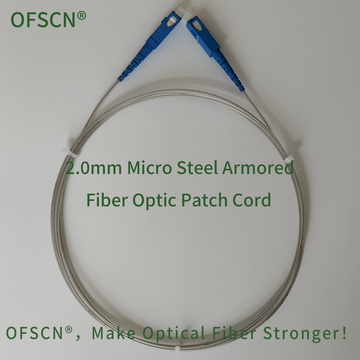
- Rigid Mechanical Armoring Isolation: Encapsulate and isolate the bare optical fiber using high-rigidity, high-lateral-pressure-resistant seamless metal micro-tubes to eliminate direct stress transmission from external rough interfaces or local lateral pressures to the glass fiber.
Related Official Specification Products:
-
Bend-Optimized Fiber : OFSCN® G.657 Optical Fiber
-
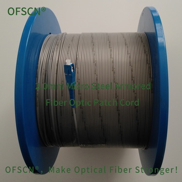
Anti-Microbending Lateral Pressure Armored Patch Cord : OFSCN® 2.0mm Micro Steel Armored Fiber Optic Patch Cord