I’ve now purchased a 4-channel demodulator; what should I do if I want to expand to 16 channels in the future?
In Fiber Bragg Grating (FBG) sensing technology, it’s crucial to strictly distinguish between two fundamental concepts: “Physical Channels” and “Number of Measurement Points (Number of FBG Sensors)”.
- Physical Channel: Refers to an independent optical transceiver interface on the FBG interrogator panel.
- Number of Measurement Points: Refers to the quantity of actual Bragg fiber grating sensor points deployed in the system.
A 4-channel FBG interrogator can, in the vast majority of engineering scenarios, directly support 16 (or even more) measurement points without necessarily requiring hardware replacement. For the requirement of expanding from a “4-channel interrogator to 16 measurement points,” there are three mainstream engineering implementation methods:
Method 1: Wavelength Division Multiplexing (WDM) Single-Channel Series Connection (Preferred Solution, No Additional Hardware Cost)
A core advantage of Fiber Bragg Gratings is their support for Wavelength Division Multiplexing (WDM). Multiple fiber gratings with different initial center wavelengths can be connected in series within a single optical fiber.
- Principle: The typical wavelength working window for the OFSCN® Fiber Bragg Grating Interrogator is 1525\sim 1565\text{ nm} (a bandwidth of 40\text{ nm}). If the 16 measurement points are evenly distributed across 4 physical channels, each channel only needs to accommodate 4 measurement points (4 \times 4 = 16 measurement points in total).
- Wavelength Planning: Within the 40\text{ nm} bandwidth, accommodating 4 measurement points means each point can be allocated an average wavelength interval of nearly 10\text{ nm}. This provides an extremely generous range for wavelength drift due to temperature or strain changes (e.g., conventional temperature sensor sensitivity is around 10\text{ pm/}^\circ\text{C}, and strain sensitivity is approximately 1.2\text{ pm/}\mu\varepsilon), preventing spectral overlap interference between measurement points.
- Implementation: Simply order custom FBG Arrays with 4 different center wavelengths from the manufacturer and connect them directly to the existing 4 channels.
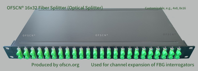
Method 2: Using Fiber Splitters for “Multi-Channel Expansion” (Star Topology Wiring)
If the 16 measurement points are located in different physical directions and cannot be strung together via a single fiber, fiber splitters can be used to expand a single physical optical path into multiple physical branches.
- Principle: Connecting a splitter (e.g., a 1\times 2 or 1\times 4 splitter) allows the optical signal output from the interrogator to be distributed evenly among multiple independent fiber pigtails. These signals are then combined at the reflection end to be demodulated by the same channel.
- Wavelength Limitation (Core Design Redline): Fiber splitters expand physical wiring channels, but from the interrogator’s logical perspective, they still belong to the same wavelength channel. Therefore, all FBG measurement points connected to the different branches of the same splitter must still have their operating wavelengths staggered and cannot be duplicated.
Related Product Reference: OFSCN® Optical Fiber Splitter
Method 3: Upgrading/Replacing the Interrogator with More Physical Channels
If the physical locations of the 16 measurement points are completely dispersed, the measurement points have extremely large dynamic ranges (causing excessive wavelength drift that prevents wavelength reuse within the same channel), or all sensors are standard off-the-shelf units with identical wavelengths:
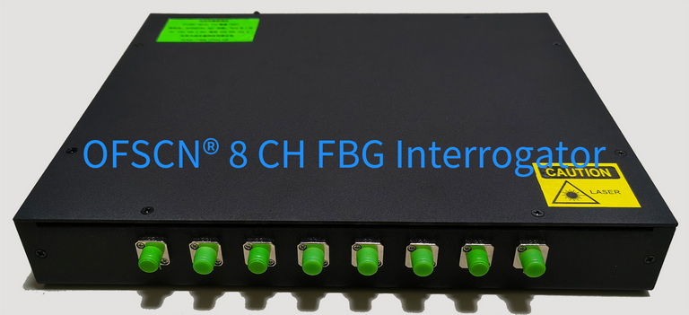
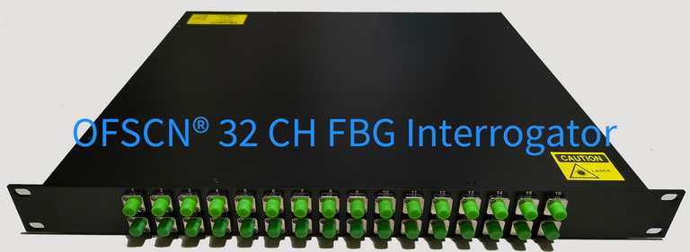
- In this case, the physical channels become the hard bottleneck, requiring equipment with 16 independent physical channels.
- Beijing Dacheng Yongsheng Technology Co., Ltd.'s interrogator hardware offers custom specifications such as 4-channel, 8-channel, 16-channel, and 32-channel.
Related Product Reference: OFSCN® Fiber Bragg Grating Interrogator
Summary Recommendation
When evaluating expansion solutions, it is recommended to prioritize the wavelength allocation plan to connect 4 sensors with different wavelengths per channel (Method 1). This is the standard engineering approach with the lowest cost and simplest wiring. Only consider adding fiber splitters (Method 2) or replacing the hardware with a multi-channel unit (Method 3) if the wiring paths are dispersed and serial connection is inconvenient.