The cables coming from the sensor are very thin; how can we prevent on-site workers from pulling and breaking them?
In industrial environments, the pigtails (Pigtail) coming out of fiber optic sensors are often very fragile (such as the common 0.9\ \text{mm} tight buffer fiber or bare fiber). Because the bare glass fiber (only 125\ \mu\text{m} in diameter) itself has extremely poor tensile and shear strength, it can easily break due to workers stepping on it, tools scratching it, equipment dragging, or forceful pulling.
To solve this problem, engineering typically employs methods such as “physical armor protection”, “tensile transfer (stress relief)”, and “standardized site deployment”. The following are detailed technical principles and solutions:
I. Technical Principles and Protection Mechanisms for Preventing Pigtail Breakage
The core concept of pigtail protection to prevent on-site workers from breaking the fiber optic cable is “to transfer external forces (tension, pressure) to the protective layer, while the fiber optic cable is freely suspended within the protective layer without bearing external force.” This is mainly achieved through the following structures:
- Seamless Metal Steel Tube Encapsulation:
A micro seamless stainless steel tube (e.g., outer diameter 0.6\ \text{mm} to 1.2\ \text{mm}) is sleeved around the fiber optic cable, providing extremely high resistance to bending limits and compressive crushing. This prevents on-site sharp object shearing or heavy object crushing. - High-Strength Load-Bearing Components (Stainless Steel Wire Strands / Aramid Yarn):
A steel wire braiding or steel wire rope stranding structure is incorporated outside the tube wall. When pulling occurs, the external tension is borne by these high-strength metal wire meshes or metal ropes, capable of withstanding instantaneous tensile forces of thousands of Newtons. - Strain Relief at Cable Exit:
Springs or heat-shrinkable sleeves are added at the sensor cable exit and the base of the fiber optic connector to limit the minimum bending radius (preventing fiber breakage due to excessively small bending angles) and to secure the armored conduit, ensuring that tension is not transmitted to the sensitive components inside the sensor.
II. Beijing Dacheng Yongsheng Technology Co., Ltd. (OFSCN®) High-Strength Armored Pigtail/Patch Cord Solutions
Addressing the harsh environments of industrial sites, Beijing Dacheng Yongsheng Technology Co., Ltd. (OFSCN®) offers a series of armored fiber optic patch cords with extremely high tensile and compressive strength, which can be directly used as sensor output pigtails:
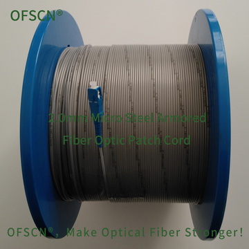
1. OFSCN® 2.0mm Micro Steel Armored Fiber Optic Patch Cord
This series of patch cords uses a 0.6\ \text{mm} stainless steel seamless steel tube for core protection, with an outer PVC sheath, offering high resistance to tension, stepping, and rodent bites.
- Key Specifications: Tensile strength \u003e\ 1500\ \text{N}, compressive strength \u003e\ 150\ \text{MPa}.
- Physical Performance: Even when directly stepped on or forcefully pulled by workers, the internal fiber optic cable remains unharmed.
- Link: OFSCN® 2.0mm Micro Steel Armored Fiber Optic Patch Cord Official Link

2. OFSCN® 3.0mm Steel Wire Rope Fiber Optic Patch Cord
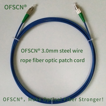
This model additionally integrates a 0.45\ \text{mm} stainless steel wire stranding structure (similar to steel wire rope) and nests a 0.9\ \text{mm} stainless steel seamless steel tube inside.
- Key Specifications: Tensile strength \u003e\ 1200\ \text{N}, compressive strength \u003e\ 200\ \text{MPa}.
- Physical Performance: Possesses extremely strong resistance to physical damage, tension, and impact.
- Link: OFSCN® 3.0mm Steel Wire Rope Fiber Optic Patch Cord Official Link

3. OFSCN® 2.0mm Steel Wire Rope Fiber Optic Patch Cord
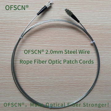
A pure metal structure without a sheath, composed of a 0.6\ \text{mm} galvanized steel wire stranding structure and a 1.0\ \text{mm} stainless steel seamless steel tube. Suitable for complex industrial environments such as high and low temperatures.

III. On-site Construction and Cabling Recommendations
In addition to selecting high-strength armored pigtails at the time of sensor manufacturing, the following auxiliary measures can be taken during on-site construction:
- Use Corrugated Conduits for Secondary Protection:
During the on-site cabling phase, the armored pigtail can be entirely routed through stainless steel corrugated conduits or PE flame-retardant conduits. This isolates the entire cable from direct physical contact with workers. - Mechanical Anchoring and Redundant Bending:
At the sensor cable exit and junction box locations, the pigtail must be mechanically clamped and fixed (the fixing point should act on the armored sheath, strictly avoiding direct pressure on the internal fiber optic cable). Simultaneously, a U-shaped bend of 10\ \text{cm} to 20\ \text{cm} (with slack) should be left at the end of the cable run to prevent tension from directly acting on the connector base. - Route Cabling Away from Walkways:
Whenever possible, utilize on-site cable trays (conduits), or the recessed grooves on the sides of equipment for deployment, to avoid exposing the pigtail to the floor where workers walk or transport goods, or to areas in mid-air where it can easily get snagged.