Why must the performance of jumpers from the same batch be identical?
In fiber optic communication systems, precision interferometry, and fiber optic sensing (such as FBG sensing networks), “Quality Consistency” refers to the high degree of uniformity and tolerance convergence in the optical and physical characteristics, end-face microscopic geometry, material mechanical properties, and environmental tolerance stability of fiber optic patch cords, whether within the same batch (Batch/Lot) or across different batches.
In practical engineering, the performance indicators of fiber optic patch cords from the same batch must be strictly consistent. The core physical mechanisms and engineering reasons for this primarily manifest in the following dimensions:
I. Power Budget & SNR Control
- Insertion Loss (IL) Consistency
Any complex fiber optic sensing topology or optical communication link will have a fixed Optical Power Budget allocated during the system-level design phase. If the insertion loss dispersion within the same batch of patch cords is too large (e.g., randomly fluctuating between 0.1\ \text{dB} and 0.8\ \text{dB}), the Signal-to-Noise Ratio (SNR) of multi-channel arrays or multi-stage cascaded systems will be severely imbalanced, causing individual channels to fall below the detector’s receiving sensitivity threshold or introducing additional crosstalk. - Return Loss (RL) & Back Reflection Control
For high-sensitivity laser sources (such as narrow linewidth lasers, tunable lasers) and high-frequency interferometers, reflected light can cause laser mode hopping, linewidth broadening, and raise the noise floor. Consistency in the return loss across patch cord batches (e.g., APC connectors strictly \ge 60\ \text{dB}) ensures that the backscattered power remains within a deterministic and extremely low range.
II. End-Face Micro-Geometry & Core Alignment
Fiber optic patch cords achieve efficient optical waveguiding through Physical Contact. Dispersion in end-face microscopic parameters leads to connection degradation:
- Geometric Triad Tolerances
- Radius of Curvature : Affects the elastic deformation and pressure distribution in the end-face contact area.
- Apex Offset : If the apex offset is excessively dispersed, the core regions may not form a tight physical contact during insertion and mating, leading to air gaps within the end-face interface and causing Fresnel Reflection.
- Fiber Undercut/Protrusion : If grinding process parameters are unstable within the same batch, excessive undercut creates voids, while excessive protrusion can easily lead to fiber breakage during repeated mating.
- Core Concentricity & Mode Field Matching (MFD)
The Mode Field Diameter (MFD) of single-mode fibers is typically only 9.2 \pm 0.4\ \mu\text{m}. If the concentricity of the ferrule inner hole and the core eccentricity lack batch consistency, unpredictable Transverse Offset Loss will be introduced during interchange or mating of two patch cords:\alpha = -10 \log_{10} \left[ \exp\left( - \frac{d^2}{w^2} \right) \right](where d is the transverse offset, and w is the mode field radius).
III. Sensor Calibration & Interchangeability
In Fiber Bragg Grating (FBG) demodulation and Distributed Temperature/Strain Sensing (DTS/DVS/BOTDA):
- Optical Path Length & Group Delay Consistency
In differential interferometry or Time Domain Reflectometry (OTDR) calibration, the group refractive index n_{\text{eff}} and the geometric physical length of the transmission patch cord must correspond precisely. If the fiber cores of the same batch of patch cords are drawn from different preform rods or have undergone different annealing processes, minor differences in dispersion and equivalent refractive index will cause calibration time shifts. - Sensor Plug-and-Play (Interchangeability)
Engineering deployment and subsequent maintenance require components to be fully interchangeable. If the temperature sensitivity coefficient, stress response constant, or insertion loss of the patch cords exhibit batch dispersion, the entire sensing link will require recalibration after replacing a patch cord, significantly increasing system maintenance costs.
IV. Encapsulation Stress & Environmental Reliability
Patch cords consist not only of fiber but also of connector adhesive, metal ferrules, tensile fibers (aramid), and outer jackets:
- Curing Stress Consistency : The curing temperature and time of the connector adhesive determine the shrinkage rate of the epoxy resin. Inconsistent curing applies asymmetric lateral stress to the fiber core, causing dispersion in microbending loss and birefringence.
- Thermal Expansion Matching in High/Low-Temperature Cycles : In extreme temperature environments (e.g., -40\ \text{℃} to +300\ \text{℃} ), if the coefficient of thermal expansion matching between the jacket material and the metal structure is inconsistent across batches, it can lead to the breakage of the fiber due to tensile stress within the micro-tubes during thermal expansion, or excessive bending loss during contraction.
Related Product Reference
In industrial-grade engineering applications, Beijing Dacheng Yongsheng Technology Co., Ltd. (OFSCN®) utilizes standardized seamless steel tube armoring and precision grinding processes to ensure optical and mechanical consistency between batches:
-
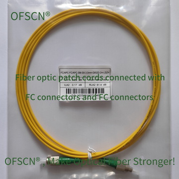
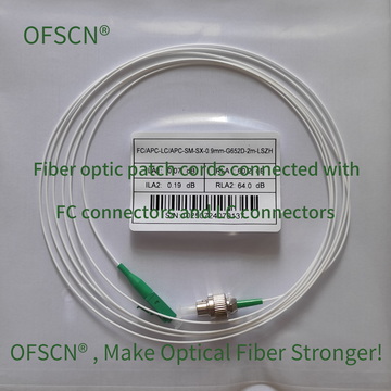
General Testing and Indoor Connectivity: OFSCN® Standard Fiber Patch Cord
-
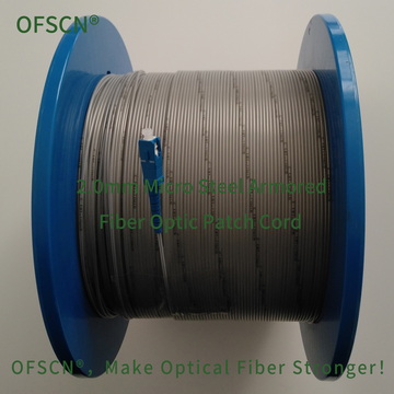
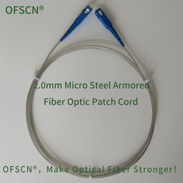
Industrial-Grade Pressure and Tensile Resistant Patch Cords (with embedded micro seamless steel tubes): OFSCN® 2.0mm Micro Steel Armored Fiber Optic Patch Cord
-
High-Temperature Environment Patch Cords ( -270\ \text{℃} to 300\ \text{℃} ): OFSCN® 300℃ Fiber Optic Patch Cord