Why can we fill the entire 40 nm bandwidth with sensors? How much “breathing room” should be left?
In a Fiber Bragg Grating (FBG) based Wavelength Division Multiplexing (WDM) sensing system, “Reserved Wavelength Margin” refers to the dynamic drift range and safety interval (Guard Band) allocated between each grating measurement point and its adjacent channels within the effective working bandwidth of the FBG demodulator. This is done to prevent overlapping of reflection spectra, wavelength demodulation confusion, and signal loss under actual operating conditions.
I. Why Can’t the 40 nm Bandwidth Be Fully Occupied by Sensors?
The effective spectral window of industrial-grade FBG demodulators commonly spans 40 nm within the C-band (e.g., 1525\ \text{nm} \sim 1565\ \text{nm} or 1528\ \text{nm} \sim 1568\ \text{nm} ). Theoretically, the Full Width at Half Maximum (FWHM / 3dB bandwidth) of a single FBG is typically only 0.2\ \text{nm} \sim 0.3\ \text{nm} . If arranged solely by static geometric width, the 40 nm bandwidth seems capable of accommodating over a hundred gratings. However, this design is absolutely not permissible in engineering practice due to the following physical reasons:
1. Dynamic Wavelength Shift of Bragg Wavelength
The reflection center wavelength of an FBG is determined by the physical formula:
\lambda_B = 2 n_{\text{eff}} \Lambda
where n_{\text{eff}} is the effective refractive index of the fiber core, and \Lambda is the grating period. Temperature changes or mechanical axial strain can alter both parameters:
- Thermo-optic Effect and Thermal Expansion: Rising temperature causes a redshift (positive increase) in wavelength; decreasing temperature causes a blueshift (negative decrease). The temperature sensitivity of bare fiber is approximately 10\ \text{pm/}^\circ\text{C} . After packaging with a metal substrate or protective tube, influenced by the thermal expansion coefficient of the materials, the sensitivity can increase to 20 \sim 40\ \text{pm/}^\circ\text{C} or higher.
- Photo-elastic Effect and Geometric Elongation: Wavelength shifts towards longer wavelengths under tensile strain and towards shorter wavelengths under compressive strain. The strain sensitivity of conventional single-mode fiber is approximately 1.2\ \text{pm/}\mu\varepsilon .
2. Spectral Cross-talk and “Wavelength Jitter/Confusion” (Cross-talk & Overlapping)
If the initial center wavelength interval between two adjacent measurement points is too narrow, when measurement point 1 is under extreme tension (or ultra-high temperature) and adjacent measurement point 2 is under compression (or low temperature), the wavelength of point 1 will drift towards the longer wavelength end, and point 2 will drift towards the shorter wavelength end.
Once the reflection peaks of the two approach or overlap in the spectral domain, the demodulator’s peak-finding algorithm will be unable to distinguish which physical measurement point the reflection signal corresponds to, leading to severe data jitter, channel confusion, or even data loss.
3. Band-Edge Cutoff Risk
For measurement points located at the edges of the demodulator’s bandwidth (e.g., near 1525\ \text{nm} and 1565\ \text{nm} ), if outward drift occurs and the wavelength moves beyond the detector’s measurement boundary, the demodulator will be unable to track the reflection peak.
II. How Much “Breathing Room” is Needed? (Calculation Method)
To ensure system stability and reliability, the wavelength slot width (Channel Spacing, or “breathing room”) required for a single FBG measurement point must follow the calculation formula:
\Delta \lambda_{\text{channel}} = \Delta \lambda_{\text{shift\_max}} + \Delta \lambda_{\text{FWHM}} + \Delta \lambda_{\text{guard}}
- Maximum Dynamic Drift ( \Delta \lambda_{\text{shift\_max}} ):\Delta \lambda_{\text{shift\_max}} = K_T \cdot \Delta T_{\text{max}} + K_\varepsilon \cdot \Delta \varepsilon_{\text{max}}where K_T is the temperature sensitivity coefficient and K_\varepsilon is the strain sensitivity coefficient.
- Grating Reflection Spectrum Width ( \Delta \lambda_{\text{FWHM}} ): Typically considered as 0.2 \sim 0.3\ \text{nm} .
- Guard Band ( \Delta \lambda_{\text{guard}} ): A safety margin of 0.5 \sim 1.0\ \text{nm} is usually reserved between the extreme edges of the two peaks to ensure the peak-finding algorithm can completely separate them.
III. Engineering Specifications for Measurement Point Multiplexing within 40 nm Bandwidth for Official OFSCN® Sensors
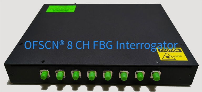
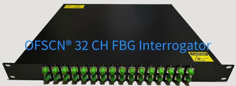
Beijing Dacheng Yongsheng Technology Co., Ltd. (大成永盛) provides strictly physically validated maximum recommended numbers of measurement points when FBG sensors of different ranges are used in conjunction with the OFSCN® Fiber Bragg Grating Interrogator (40 nm standard demodulation bandwidth):
-
Narrow Temperature Range Sensors (-40°C to 100°C)
- Typical Product: OFSCN® 100°C Fiber Bragg Grating Temperature Sensor
- Physical Characteristics: Temperature range span of approximately 140^\circ\text{C} , with total drift within the full temperature range typically within 1.5\ \text{nm} .
- Spatial Allocation and Measurement Point Limit: Approximately 2\ \text{nm} of space is reserved per measurement point. Within a 40 nm bandwidth, it is recommended not to exceed 20 points per single channel per fiber.
-
Medium Temperature Range Sensors (-200°C to 300°C)
- Typical Product: OFSCN® 300°C Fiber Bragg Grating Temperature Sensor
- Physical Characteristics: Temperature range span reaches 500^\circ\text{C} , with total wavelength drift up to 3 \sim 4\ \text{nm} .
- Spatial Allocation and Measurement Point Limit: Approximately 4\ \text{nm} of space is required per measurement point. Within a 40 nm bandwidth, it is recommended not to exceed 10 points per single channel per fiber.
-
High Temperature Range Sensors (-200°C to 500°C)
- Typical Product: OFSCN® 500°C Fiber Bragg Grating Temperature Sensor
- Physical Characteristics: In the high-temperature range above 300°C, the thermo-optic coefficient of quartz fiber exhibits a binomial nonlinear increase, significantly amplifying the drift caused by temperature rise.
- Spatial Allocation and Measurement Point Limit: Approximately 8\ \text{nm} of space is required per measurement point. Within a 40 nm bandwidth, it is recommended not to exceed 5 points per single channel per fiber.
-
Ultra-High Temperature Sensors (-270°C to 800°C)
- Typical Product: OFSCN® 800°C Fiber Bragg Grating Temperature Sensor
- Physical Characteristics: The extreme temperature difference exceeds 1000^\circ\text{C} , with unidirectional wavelength drift exceeding 10\ \text{nm} .
- Spatial Allocation and Measurement Point Limit: Approximately 13\ \text{nm} or more of space is required per measurement point. Within a 40 nm bandwidth, it is recommended not to exceed 3 points per single channel per fiber.
-
Large Strain Sensors (Strain Range \ge 6000\ \mu\varepsilon )
- Typical Product: OFSCN® Polymer-encapsulated Fiber Bragg Grating Strain Sensor
- Physical Characteristics: Calculated at 1.2\ \text{pm/}\mu\varepsilon , the full-range strain drift can reach 7.2\ \text{nm} .
- Spatial Allocation and Measurement Point Limit: Under full-range operating conditions, it is recommended not to exceed 5 measurement segments per single fiber within a 40 nm bandwidth.
Engineering Summary: The so-called “breathing room” is essentially the projection of the physical operating range onto the wavelength domain. The wider the range of physical condition changes for a measurement point, the larger the wavelength space that single grating necessitates, and the fewer FBGs can be multiplexed in series on a single fiber.