1. The Physics of Fiber Optic Breakage Under Tension
The core material of optical fibers is typically high-purity silicon dioxide ( \text{SiO}_2 ) glass. Although single-crystal silicon or quartz theoretically possess extremely high intrinsic tensile strength (reaching several \text{GPa} levels), in practical engineering fabrication and usage, microscopic sub-micron cracks (Griffith cracks) are inevitably present on the fiber surface.
Under axial tensile force, severe stress concentration occurs at the tips of these microcracks. When the local stress intensity factor reaches the critical value of the material’s fracture toughness, the crack expands unstably at acoustic speeds, leading to instantaneous brittle fracture of the fiber. In its unprotected bare fiber state, the ultimate tensile strain limit is typically only around 0.5\% \sim 1\% (equivalent to 5000\ \mu\varepsilon \sim 10000\ \mu\varepsilon ).
2. Engineering Design Principles for Protecting Optical Fibers from Breakage Through Encapsulation
To prevent optical fibers from breaking under external forces, engineering primarily employs several encapsulation structures and physical mechanisms. The core idea is “stress redistribution”, “strain buffering”, and “stiffness matching”:
A. Stiffness Sharing and High-Strength Casing Protection
This is the most common and effective method for protecting optical fibers. It involves inserting the bare fiber into a protective sheath with extremely high mechanical strength and large elastic modulus (such as seamless steel tubes, elastic alloy tubes, fiberglass, etc.).
- Physical Mechanism: External tensile force acts on the entire encapsulated assembly. Because the product of the cross-sectional area and elastic modulus (tensile stiffness EA) of the metal or high-strength protective tube is far greater than that of the optical fiber, the vast majority of the axial tensile force is borne by the high-strength metal casing. The axial tensile stress transmitted to the internal optical fiber is controlled at a very low level.
B. Polymer Elastomer Damping and Shear Buffering
If the encapsulated assembly needs to measure the deformation of external structures (e.g., strain sensors), the fiber cannot be completely suspended. Instead, the strain needs to be transferred to the fiber through the encapsulation material. In this case, polymer composite structures are used.
- Physical Mechanism: A layer of special polymer material (such as polyimide, high-performance epoxy resin, etc.) is filled between the optical fiber and the metal protective tube. Polymer materials have good viscoelasticity and shear deformation capabilities. When external deformation or transient tensile impact occurs, the polymer buffer layer can uniformly disperse the concentrated stress along the axial direction of the optical fiber, preventing localized fracture caused by sudden shear or tensile stress.
C. Loose Tube Design and Excess Length Reserve
For scenarios that only require optical signal transmission (like communication or temperature sensing) and do not require strain measurement under tension, a “loose tube” encapsulation is used.
- Physical Mechanism: The optical fiber is placed in a tube with an inner diameter larger than the outer diameter of the fiber (usually filled with fiber paste), and the fiber is given a certain “excess length” within the tube (meaning the actual length of the fiber is slightly greater than the axial length of the tube). Additionally, aramid yarns (Kevlar) or high-strength steel wires are added to the optical cable. When the tube as a whole is stretched, as long as the elongation does not exceed the physical excess length of the fiber, the fiber only undergoes straightening movement within the tube and does not bear any tensile stress, thereby ensuring that the fiber is never pulled to break.
3. Industrial-Grade Encapsulated Sensor Cases Related to OFSCN® (Dacheng Yongsheng)
To achieve stable and breakage-resistant measurements in various complex industrial environments with high tensile forces, OFSCN® (Beijing Dacheng Yongsheng Technology Co., Ltd.) has developed multiple high-strength metal tube and polymer composite encapsulation solutions. You can refer to the following product structural designs:
Solution 1: Polymer Sealing + Seamless Steel Tube Protection Structure
For harsh environments with large deformation and waterproofing requirements, polymer materials are used for primary sealing, with a seamless steel tube wrapped externally for secondary reinforcement. This provides good elastic transfer while possessing a high tensile limit.
For example, the OFSCN® Polymer-encapsulated Fiber Bragg Grating Strain Sensor (0.7mm/1.2mm diameter) encapsulates fiber Bragg gratings with polymer material and adds a seamless steel tube outside the polymer. The outer diameter is increased from the original \le 0.7\ \text{mm} to \le 1.2\ \text{mm}, significantly enhancing tensile strength and resistance to breakage.
Its larger-sized product, the OFSCN® Polymer-encapsulated Fiber Bragg Grating Strain Sensor (1.5mm/2.3mm diameter), incorporates a thick-walled seamless steel tube, making it more suitable for high-strength, high-tensile-force extreme outdoor applications and embedded installations within structural components.
Solution 2: Precision Elastic Alloy Tube Encapsulation Structure
For precise dynamic or static strain measurements that also require prevention of breakage, elastic alloy tubes are typically used for encapsulation.
For example, the OFSCN® Alloy Tube Packaged Fiber Bragg Grating strain sensor uses a precision elastic alloy tube with an outer diameter of \le 1.1\ \text{mm}. This not only effectively protects the internal fiber Bragg grating from damage due to localized micro-stress concentration but also ensures that the fiber does not break under large strains within the measurement range of \ge 6000\ \mu\varepsilon.
Solution 3: Composite Encapsulation Structure with Ultra-Large Range Elastomer and Alloy Tube
For strain measurements with extremely large tensile ranges:
The OFSCN® Ultra-Large Range Fiber Bragg Grating Strain Sensor features a composite encapsulation design combining an elastic alloy tube with special large-elasticity elastomer material. This structure uniformly releases and disperses extremely large axial displacements over a wider range, physically preventing the localized breakage of the optical fiber when subjected to large-span tensile forces.
Solution 4: Micro All-Metal Alloy Tube Distributed Strain Encapsulation (Suitable for OFDR)
For distributed strain measurements requiring high spatial resolution:
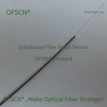
The OFSCN® 85°C OFDR Micro All-Metal Strain Sensor utilizes a single-layer elastic alloy tube with an outer diameter of only 0.6\ \text{mm} for encapsulation. It is specifically designed for distributed sensing based on OFDR technology. While ensuring extremely high tensile strength and breakage resistance, it minimizes the casing thickness and volume to the utmost extent, thereby greatly enhancing the sensor’s sensitivity.
Conclusion
To protect optical fibers from breaking under immense tensile forces, the core encapsulation strategy lies in selecting appropriate stress redistribution mechanisms based on the application:
- Temperature / Signal Transmission: The preferred structure is unconstrained loose tube armored + aramid tensile core, allowing the fiber axial slack and completely isolating it from tensile load.
- Precision Strain / Force Measurement: The preferred method is composite encapsulation with seamless steel tubes / elastic alloy tubes + polymer materials. By controlling the cross-sectional area and tensile stiffness (EA) of the tubing, the tube body bears the majority of the axial tensile force while ensuring safe and accurate transfer of strain signals.