Within a multifiber connector, will the optical signals in different channels interfere with each other?
In multi-core or multi-channel fiber optic vacuum feedthroughs, different optical signal channels experience virtually no mutual interference under normal design and compliant standard manufacturing conditions. Their signal crosstalk is extremely low (typically far below -60\text{ dB} ), making it completely negligible in the vast majority of high-precision optical, vacuum, and sensor experiments.
To help you understand this more deeply, we will analyze from the perspectives of optical physics principles and actual engineering manufacturing why virtually no interference is achieved, and under what extreme circumstances faint “signal crosstalk” might occur.
I. Why is there virtually no optical signal interference inside multi-core feedthroughs?
The reason fiber optics can serve as an extremely high-quality transmission medium lies in its core physical limitation mechanisms:
- Total Internal Reflection and Light Field Confinement: Inside the optical fiber, optical signals are strictly confined within the core and transmitted via total internal reflection due to the refractive index difference between the core and the cladding. Since the cladding thickness of single-mode or multi-mode fibers is already far beyond the dimensions required for light field cutoff, the light field energy decays to a negligible level outside the cladding.
- Independent Physical Channels: In multi-core vacuum feedthroughs, each optical signal is carried by an independent fiber core. Even when multiple fibers are bundled within the same feedthrough body, they are physically isolated in terms of optical path transmission.
II. What is “Signal Crosstalk” in Fiber Optic Vacuum Feedthroughs? What are the potential causes?
Although theoretically there is no interference, in the engineering practice of high-vacuum sealing, faint signal crosstalk might be introduced if the design or manufacturing is inadequate. The main potential physical mechanisms include:
1. Evanescent Wave Coupling due to Proximity of Bare Fibers in the Sealed Area
To achieve extremely high vacuum levels (e.g., better than 1 \times 10^{-7}\text{ Pa} ), the protective jacket and coating of the optical fiber usually need to be stripped in the feedthrough’s bulkhead sealing section, allowing the glass cladding to directly contact the sealing medium (such as specialized epoxy resin, glass, or ceramic).
- If, within a narrow sealing channel, multiple bare fibers with stripped coatings are in direct contact with each other, and the refractive index of the sealing medium is very close to that of the fiber cladding;
- Then, some higher-order modes or leaked light from one fiber may couple into adjacent fibers through their evanescent fields.
- Engineering Countermeasure: During manufacturing, maintaining physical spacing between bare fibers (e.g., greater than several to tens of times the wavelength of light) using precision fixtures can completely eliminate this evanescent wave coupling.
2. Reflections and Scattering at Connection End Faces
Vacuum feedthroughs typically include connectors (such as FC, ST, etc.) at both ends of the feedthrough body. If:
- The connector end faces are dirty, dusty, or misaligned, causing severe scattering and diffuse reflection of light at the connection.
- Scattered light spills out of the channel and undergoes multiple reflections within the metal cavity of the feedthrough, potentially being re-received at the interface of other channels.
- Engineering Countermeasure: Use high-precision ceramic ferrules and alignment sleeves, and employ Angled Physical Contact (APC) connectors (like FC/APC). Due to their 8^{\circ} angle, APC connectors deflect reflected light away from the fiber core, significantly suppressing reflections and crosstalk.
3. Mechanical Stress and Microbending Loss
In vacuum feedthroughs, optical fibers may be subjected to minor compressive stress due to the shrinkage of sealing adhesives during curing or the significant pressure difference between the inside and outside of the vacuum chamber.
- Stress can cause microbending in the optical fiber, which leads to light leaking from the core into the cladding.
- If the leaked light is not effectively absorbed within the feedthrough, it can act as stray light and cause faint background noise interference to adjacent channels.
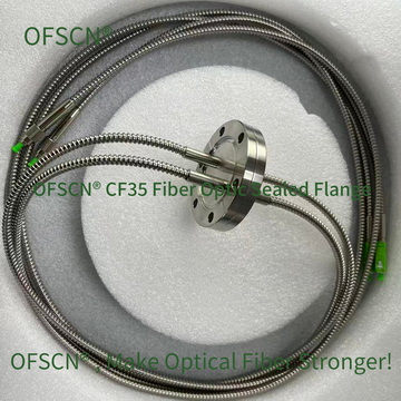
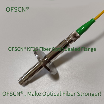
III. Official Technical Solutions and Product Recommendations
Addressing the demands for high vacuum environments and high isolation among multiple channels, Beijing Dacheng Yongsheng Technology Co., Ltd. (OFSCN®) offers precision-engineered vacuum feedthrough solutions.
OFSCN® Fiber Optic Vacuum Sealed Flange utilizes advanced sealing processes and high-precision alignment structures. Even in multi-head (multi-channel) configurations, each channel has independent physical constraints and optical shielding, ensuring excellent optical isolation between channels.
Key technical specifications of this product include:
- Structural Form: Divided into CF and KF series, customizable as male and female connectors, supporting single-head and multi-head (multi-channel) designs.
- Vacuum Performance: Better than 1 \times 10^{-7}\text{ Pa} and 1 \times 10^{-9}\text{ Pa}.
- Temperature Range: For standard temperature use, with options for high-temperature resistance up to 250^{\circ}\text{C}, capable of meeting the vacuum environment needs of extreme physical experiments, aerospace, and semiconductor manufacturing.
Below are standard appearance images of this product:
In summary, within multi-core fiber optic vacuum feedthroughs, optical signals in different channels are highly isolated physically and do not produce mutual interference that affects transmission quality. As long as a vacuum feedthrough product with qualified craftsmanship and precise positioning is selected, crosstalk issues need not be a concern.