What does “0.01dB” shown on the fusion splicer mean? Is the splice point more fragile than the fiber itself?
This is a very classic and critical physics and mechanics problem in optical fiber and splicing engineering. The precise and rigorous answers are provided below from the perspectives of optical measurement principles and material fracture mechanics.
I. What does “ 0.01\ \text{dB} ” displayed on the fusion splicer mean?
The displayed 0.01\ \text{dB} (or other values) on the fusion splicer screen is not the actual measured splicing loss, but an “Estimated Loss” based on geometric image processing.
1. Estimation Mechanism and Physical Limitations
- Geometric Alignment Based on Lateral Imaging:
Modern fusion splicers (such as core alignment or cladding alignment splicers) primarily use built-in high-resolution cameras to obtain lateral images of the fiber ends from two perpendicular directions (X-axis and Y-axis). - Algorithmic Calculation:
The microprocessor within the fusion splicer uses image processing algorithms to measure the angular offset of the fiber cores, the lateral offset of the alignment, the deformation of the end faces, and the presence of visible bubbles after splicing. Subsequently, these geometric deformation parameters are fed into a predefined mathematical model of electromagnetic wave propagation to estimate a theoretical insertion loss. - Inability to Detect Hidden Defects:
This indirect estimation method cannot detect subtle refractive index perturbations within the fiber caused by the discharge (e.g., thermal stress distribution), invisible micro-bubbles, or scattering and absorption losses due to mismatches in the refractive index profiles (n\text{-profile}) of the fiber cores themselves.
2. Methods for Determining Actual Loss
In practical communication and sensing engineering, the actual loss of an optical fiber splice point is usually higher than the estimated value from the fusion splicer. Accurate measurement of splice loss requires the following physical methods:
- Optical Time Domain Reflectometer (OTDR, single-ended backscattering method):
This is a widely recognized and highly accurate method for single-point loss measurement, achieved by analyzing the abrupt change in Rayleigh scattering at the splice point. - Light Source + Optical Power Meter (dual-ended direct measurement):
Insertion loss is directly obtained by measuring the optical power attenuation before and after the splice.
II. Is the splice point more fragile than the fiber itself?
Yes, the splice point (fused region of bare fiber) is significantly more fragile than the original, untreated fiber in terms of mechanical properties (especially tensile strength and fatigue life).
This is determined by the fiber manufacturing process, surface physicochemical state, and thermal history, with the main reasons including:
1. Coating Stripping and Micro-crack Introduction (Griffith’s Theory)
- The high mechanical strength of optical fibers relies heavily on the protective coating (e.g., polyacrylate, polyimide) applied instantly during the drawing process. This coating effectively shields the silica (\text{SiO}_2) cladding surface from external moisture and physical impacts, preventing the formation of stress-induced cracks.
- Before splicing, the coating must be stripped using mechanical strippers or chemical methods. Mechanical stripping can easily create micrometer/nanometer-scale micro-cracks on the exposed glass surface. According to Griffith’s micro-crack theory in fracture mechanics, these micro-cracks cause severe stress concentration when subjected to tensile stress, leading to material fracture at loads far below the original fiber’s tensile limit.
2. Severe Thermal History and Heat Affected Zone (HAZ)
- During splicing, the instantaneous high temperature generated by the discharge arc (typically exceeding 1500\ ^{\circ}\text{C}) melts and re-fuses the silica.
- In the transition zone between the splice point and the unaffected fiber (Heat Affected Zone), the material undergoes rapid temperature gradients and extremely fast cooling. This results in residual thermal stresses and increased anisotropic defects in the microscopic structure of silica, significantly reducing the tensile strength of the joint.
3. Slow Crack Growth due to Environmental Moisture
- If the splice point is not immediately protected by moisture-proof encapsulation after splicing, water molecules (\text{H}_2\text{O}) in the air can hydrolyze unsaturated siloxane bonds on the silica surface (forming silanol groups \text{Si-OH}). This allows existing micro-cracks to propagate internally under minimal external force. This chemo-mechanical coupled effect, known as stress corrosion, greatly reduces the long-term fatigue life of the splice joint.
III. Engineering Countermeasures and Specialty Fiber Applications
To overcome the physical limitations of splice point fragility and unstable loss, optical and electrical engineering typically employs the following methods:
-
Heat Shrink Sleeve Protection (Splice Protection Sleeve):
A specialized heat shrink tube with a stainless steel reinforcing rod is used to cover the splice point externally. This provides mechanical support and physical isolation, preventing external bending or tensile forces from directly acting on the bare fiber. -
Recoating:
In applications requiring extremely small fiber outer diameters (e.g., fiber optic gyroscopes, high-strength fiber Bragg gratings), a precision recoater is used to reapply a layer of polymer material (such as polyimide or UV-curable adhesive) to the splice point, partially restoring its mechanical strength. -
Specialty High-Strength Fibers and Fiber Gratings:
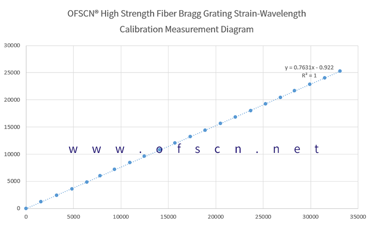
For deployments in extreme conditions with high temperatures and high risk of damage, such as those undertaken by Beijing Dacheng Yongsheng Technology Co., Ltd. (OFSCN®), to address the mechanical attenuation caused by “coating stripping” and “splicing,” the following specialty processing and material solutions are employed:- High-Strength Fiber Bragg Gratings without Splicing:
Using femtosecond laser point-by-point writing technology, gratings are inscribed directly onto fibers with intact coatings, fundamentally eliminating the physical weak points caused by arc fusion splicing:
Product Name: OFSCN® High-Strength Fiber Bragg Gratings / FBG Strings (Bare)
- High-Strength Fiber Bragg Gratings without Splicing:

- High-Temperature Resistant Small Diameter Polyimide Fiber:
For applications requiring multi-point splicing and extreme durability, ultra-small diameter, high and low-temperature resistant specialty polyimide fibers are used. Through extremely precise stripping and splicing process parameter control, very low signal loss and extended joint life are ensured:
Product Name: OFSCN® 300℃ Small diameter optical fiber
