Why can’t some demodulators find a signal after connecting 5 kilometers of optical fiber?
A common engineering problem in fiber optic sensing is that the “demodulator fails to recognize the signal after accessing 5 km of fiber.”
According to theoretical line loss calculations, standard single-mode fiber (compliant with ITU-T G.652D) has a transmission loss of approximately 0.2\ \text{dB/km} at the 1550\ \text{nm} wavelength. For a 5 km link, the total round-trip length is 10\ \text{km}, and the theoretical fiber attenuation alone is only:
10\ \text{km} \times 0.2\ \text{dB/km} \approx 2.0\ \text{dB}
With only 2.0\ \text{dB} of additional attenuation, most demodulators have ample margin. Therefore, the fundamental reason for the complete loss of signal is not the linear absorption loss of the fiber, but rather falling into the “engineering trap of Dynamic Range.”
I. What is the “Dynamic Range Trap”?
Demodulator manuals typically specify a broad “dynamic range” (e.g., 30\ \text{dB}, 40\ \text{dB}, or 50\ \text{dB}). However, in practical engineering, the specified dynamic range (the theoretical difference between the system’s full scale and noise floor) often deviates from the instantaneous working dynamic range. This primarily manifests in the following four physical mechanisms:
1. Instantaneous Dynamic Range and Saturation from Near-End Strong Reflections (Fresnel Reflection Trap)
Fiber Bragg Grating (FBG) demodulators use photodetectors (PD) and transimpedance amplifier (TIA) circuits that have a fixed linear operating range.
- Physical Phenomenon: If there is a non-angled contact fiber adapter (e.g., PC/UPC flat connector, with a surface reflectivity of about -14.7\ \text{dB} due to the air gap) or a slightly damaged end face near the link’s origin, strong Fresnel reflections will return directly to the receiver.
- Failure Mechanism: To prevent detector saturation, the demodulator’s Automatic Gain Control (AGC) will automatically reduce the reception gain significantly; or the photodetector will directly enter its nonlinear saturation region. At this point, the weak FBG reflection signal from the far end, after undergoing the 5 km round-trip attenuation, has its peak power suppressed below the system’s quantization noise (Noise Floor) or the Analog-to-Digital Converter’s (ADC) resolution limit, causing the far-end signal to be “drowned out.”
2. Accumulation of Long-Fiber Rayleigh Scattering and Background Noise Rise
- Physical Phenomenon: As light propagates within the quartz glass fiber, microscopic density non-uniformities cause continuous Rayleigh backscattering.
- Failure Mechanism: With the unidirectional fiber length extending to 5 km, the cumulative energy of continuous backscattered light along the path increases significantly. For demodulators employing a broadband light source (ASE) combined with a spectral analysis module, or certain continuous wave (CW) swept laser schemes, Rayleigh scattering forms a raised, continuous, flat DC baseline in the reception band. The dynamic range depends not only on absolute sensitivity but more crucially on the Signal-to-Noise Ratio (SNR) of the grating’s reflection peak relative to this scattered baseline. As the background light rises, the effective contrast ratio (CNR/SNR) of the true reflection peak deteriorates sharply.
3. Sampling Frequency (Speed) and Effective Dynamic Range Trade-off
- The maximum dynamic range specified by the demodulator is almost always measured under ideal conditions at the lowest sampling frequency (e.g., 1\ \text{Hz} ), with a longer detector integration time and multiple averaging filters.
- When the system operates at a higher sampling frequency (e.g., 100\ \text{Hz} or even higher dynamic sampling), the integration time per sample is reduced, the noise equivalent power (NEP) of the photoelectric reception unit increases, and the system’s effective dynamic range can decrease by 10\ \text{dB} \sim 20\ \text{dB}. If the 5 km fiber has additional connector losses, bending losses, and splitting attenuation, the signal can easily fall out of the demodulable window under high-frequency operating conditions.
4. Peak-Finding Algorithm Threshold and Reflectivity Mismatch
- The demodulator’s built-in digital signal processing (DSP) algorithms usually have fixed “Peak Detection Threshold” and “Side Mode Suppression Ratio (SMSR) determination conditions” to prevent false locking onto spurious peaks.
- If the far-end sensor uses a weak reflectivity grating (e.g., only 10\% \sim 20\% reflectivity), after the 5 km round-trip link and the insertion loss from multiple flanges along the way (each active connection point may introduce 0.3\ \text{dB} \sim 0.5\ \text{dB} loss), the returned reflection peak’s absolute power or SNR falls below the software-set hard threshold for determination, and the algorithm will directly report “no measurement point connected.”
II. Engineering Troubleshooting and Avoidance Strategies
- Unify All Link Connections to Angled Physical Contact (APC):
- Strictly replace all flanges and patch cord connections in the link with FC/APC connectors (8^\circ angled end faces). This provides a return loss better than 60\ \text{dB}, completely eliminating the blinding effect of near-end Fresnel reflections on the detector.
- Select High Reflectivity FBG Sensors for Long-Distance Links:
- For long-distance transmission, avoid using very weak reflectivity gratings. Instead, use gratings with higher reflectivity (e.g., nominal 70\%) and good side mode suppression ratio (\ge 15\ \text{dB}) to provide sufficient optical power margin to withstand along-path attenuation and Rayleigh scattering.
- Verify Actual Link Attenuation (OTDR Diagnosis):
- Use an OTDR to test the 5 km fiber optic cable and identify any points of high attenuation, such as poor fusion splices or construction-induced microbends.
- Reasonably Tune Demodulator Parameters:
- In the demodulator’s configuration software, appropriately reduce the data sampling frequency and increase the integration smoothing period. If the demodulator supports threshold configuration, manually lower the peak detection threshold based on the real-time spectrum graph.
III. Official Related Hardware Support
Beijing Dacheng Yongsheng Technology Co., Ltd.'s standard FBG sensing systems and demodulation equipment are designed with technical benchmarks for the optical budget of long-distance links:
OFSCN® Fiber Bragg Grating Interrogator
- Wavelength Operating Range: Default 1525\ \text{nm} \sim 1565\ \text{nm} or 1528\ \text{nm} \sim 1568\ \text{nm} (customizable).
- Wavelength Resolution: Default 1\ \text{pm} (customizable to 0.1\ \text{pm}).
- Sampling Frequency Configuration: Supports 10\ \text{Hz}, 50\ \text{Hz}, 100\ \text{Hz}. Customers can self-adjust down to 1\ \text{Hz} via software to obtain better SNR and sensitivity performance in long-distance, high-attenuation conditions.
- Channel Configuration: Offers 4-channel, 8-channel, 16-channel, and 32-channel customization.
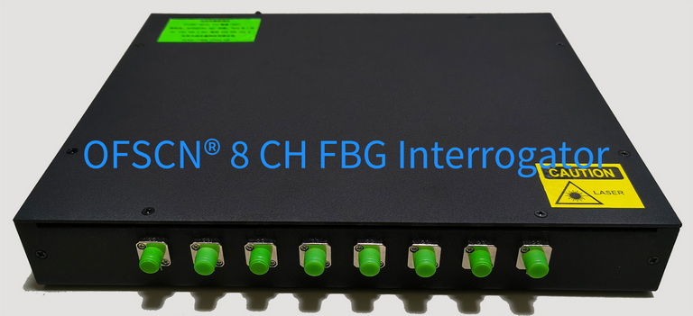
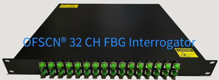
The accompanying OFSCN® Fiber Bragg Grating sensors use FC/APC fiber interfaces and 70\% reflectivity gratings (Side Mode Suppression Ratio \text{SMSR} \ge 15\ \text{dB}) by default, providing a stable spectral reflection profile and SNR margin for long-distance engineering links. For more technical insights, please refer to OFSCN® Fiber Bragg Grating Demodulator Function Summary.