To what extent can a fiber optic cable be pulled before it can no longer be retracted?
From the perspective of material physics and optical engineering, the underlying physical mechanism behind the question of “how much can an optical fiber be stretched before it can no longer return to its original shape (i.e., its elastic limit)” differs significantly from that of common metallic materials (like copper or steel wires).
In simple terms: Bare fused silica optical fiber has virtually no plastic deformation phase at room temperature where it would “fail to return to its original shape”; it either returns to its original shape intact or breaks directly. However, in practical engineering, the fiber’s coating and microscopic cracks determine its “engineering elastic limit.”
Here is a detailed analysis of the physical and engineering aspects:
1. Intrinsic Material Mechanical Properties of Fused Silica Fiber (No Plastic Deformation)
The core material for optical fiber fabrication is high-purity silicon dioxide (SiO_2) glass. At room temperature, silicon dioxide is a typical brittle material and a purely elastic material.
- No Yield Point: Unlike metals, when fused silica glass is subjected to tensile stress, the network structure formed by its siloxane tetrahedrons only undergoes elastic stretching of chemical bond angles and lengths.
- 100% Elastic Recovery: This means that as long as the tensile force does not reach its fracture limit, the bare optical fiber will recover 100% to its initial length once the external force is removed.
- Brittle Fracture: If the tensile force continues to increase, the fiber will not undergo plastic deformation, such as thinning and elongating, like metals (i.e., it won’t “fail to return to its original shape”). Instead, it will directly undergo brittle fracture (breaks upon stretching).
Therefore, solely considering the bare fused silica fiber itself, there is no intermediate state where it elongates to a certain extent, fails to return to its original shape, but has not yet broken.
2. Engineering Factors Causing Actual Fiber Damage or Failure to Return to Original Shape
In practical applications, optical fibers are not simply bare glass strands; they include a coating layer and operate within specific environments. The following factors determine their actual tensile limits:
A. Plastic Deformation of the Outer Coating Layer
During the fiber drawing process, a protective layer is applied. Common coating materials (such as polymeric materials like acrylates and polyimides, or metals like aluminum and gold) exhibit significant elasticity and plasticity:
- When the tensile strain exceeds a certain limit (typically around 0.5\% to 1\%), the coating layer enters the plastic deformation phase. Microscopic relative slippage (delamination) between the coating and the fused silica cladding may even occur.
- After the external tensile force is released, due to the permanent plastic deformation of the coating layer, it hinders the complete elastic recovery of the internal fused silica fiber. It might even apply an axial compressive stress to the fiber, causing microbending, leading to a sharp increase in fiber transmission loss or irreversible wavelength drift.
B. Microcrack Propagation (Stress Corrosion)
The surface of fused silica optical fibers inevitably has sub-micrometer-sized microcracks. When the fiber is subjected to high tension, these cracks undergo slow crack growth catalyzed by moisture in the air:
- Even if the fiber appears to retract after the tensile force is released, its surface microstructure has suffered irreversible damage, significantly reducing its mechanical strength. In subsequent use, delayed fracture is highly likely.
3. Tensile and Strain Safety Margins in Engineering Design
In practical engineering applications, optical fiber deployment, and the design of Fiber Bragg Grating (FBG) sensors, strain (measured in units of \mu\varepsilon, where 10000\ \mu\varepsilon = 1\% length deformation) is typically used as the metric:
- Factory Proof Test Limit: Commercialized optical fibers commonly undergo an instantaneous tensile screening test of 1\% (approximately 100\ \text{kpsi} axial tension) or 2\% (200\ \text{kpsi}) on the production line. Flaws exceeding this limit will break during the test.
- Long-Term Safety Limit: To ensure the optical fiber does not fracture due to stress fatigue over its 20 to 25-year lifespan, engineering practice typically requires the long-term operating strain of the fiber to not exceed 0.2\% to 0.5\% (i.e., 2000\ \mu\varepsilon to 5000\ \mu\varepsilon).
4. Related FBG Products and Their Limit Indicators
In Fiber Bragg Grating (FBG) sensors, which operate based on the principle of fiber stretching, different coating materials and packaging structures determine their maximum allowable tensile strain limits. Exceeding these limits will result in device damage or irreversible wavelength zero-point drift:
-
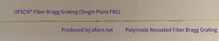
Standard Fiber Bragg Gratings (Bare Gratings):
For example, OFSCN® Polyimide Fiber Bragg Gratings / FBG Strings (Bare) or OFSCN® Polyacrylate Fiber Bragg Gratings / FBG Strings (Bare), their maximum usable strain range at room temperature is \le 10000\ \mu\varepsilon (approximately 1\% elongation).
-
Femtosecond Fiber Bragg Gratings (Bare Gratings):
OFSCN® Standard Femtosecond Fiber Bragg Gratings / FBG Strings (Bare), written using femtosecond lasers, have a maximum usable strain range at room temperature of \le 15000\ \mu\varepsilon (approximately 1.5\% elongation). -
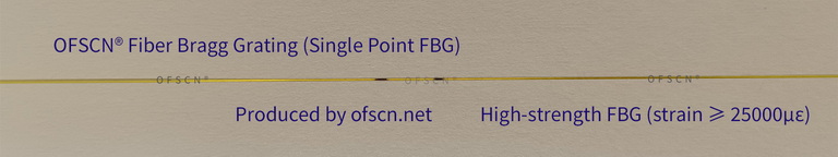
High-Strength Fiber Bragg Gratings (Bare Gratings):
OFSCN® High-Strength Fiber Bragg Gratings / FBG Strings (Bare), made from high-strength screened polyimide fiber, offer a maximum usable strain range of \ge 25000\ \mu\varepsilon (approximately 2.5\% elongation).
-
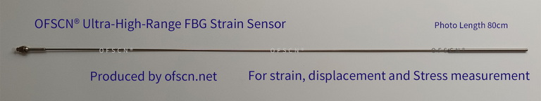
Ultra-Large Range Strain Sensors (Special Mechanical Structure Design):
When testing large deformations (e.g., 3\% to 40\% ) in large structures, directly stretching glass fibers will inevitably cause them to break. In such cases, a structural conversion design is necessary, such as the OFSCN® Ultra-Large Range Fiber Bragg Grating Strain Sensor. This sensor utilizes an elastic alloy tube and elastic encapsulation for mechanical range conversion. Its default range is \ge 30000\ \mu\varepsilon, with a maximum customizable range up to 400000\ \mu\varepsilon (i.e., deformation from 3\% to 40\% ). Its internal mechanical structure ensures safe elastic recovery within this range without permanent deformation during stretching.