How to prevent flange misalignment or seal offset?
In ultra-high vacuum (UHV) or high vacuum (HV) systems, the installation precision of Fiber Optic Vacuum Feedthroughs/Flanges directly impacts the system’s seal integrity and the mechanical robustness of the fiber. An incorrectly oriented flange or a misaligned sealing gasket can lead not only to severe leakage but also to the fracture of the internal quartz fiber due to uneven stress.
Addressing your concerns about “preventing incorrect flange orientation” and “preventing gasket misalignment,” vacuum engineering design employs well-established Poka-Yoke (error-proofing) mechanisms. Here are the specific implementation principles:
I. How to Prevent Incorrect Flange Orientation? (Anti-Reverse Design)
In practical engineering installations, the fiber optics on either side of the flange (vacuum-side vs. atmosphere-side) typically exhibit significant differences in physical characteristics, jacketing materials (e.g., seamless steel tubing or bare fiber for the vacuum side, PVC or stainless steel armor for the atmosphere side), and pigtail lengths. An incorrectly oriented flange can impair optical transmission performance or even cause damage.
-
Mechanical Asymmetry Design
- CF Series (ConFlat Flange): CF flanges feature a precision-machined knife-edge on the sealing side and a flat load-bearing surface on the back. Because the knife-edge must face and press into the copper gasket, this mechanical structure physically prevents installation in the wrong orientation.
- Asymmetrical Connector Specifications: The fiber optic connectors on both ends of the flange can be designed with different plug/socket types (e.g., male on one end, female on the other) or utilize different fiber connectors at each end (e.g., a bare ferrule on the vacuum side and a standard FC/APC connector on the atmosphere side). This makes physical connection impossible if installed in reverse.
-
Visual Indicators and Orientation Markings
- The outer wall of the flange’s metal body is typically marked with high-precision laser etching, clearly indicating “VACUUM” (vacuum side) and “ATMOSPHERE” (atmosphere side), or engraved with unidirectional arrows indicating airflow/optical path direction to aid installers in orientation verification.
II. How to Prevent Gasket Misalignment? (Anti-Shift Design)
Gasket eccentricity or slippage is a common cause of vacuum system seal failure. Error-proofing and positioning principles vary according to different flange standards:
-
Centering Design in KF Series Flanges (Klamp Flange)
- KF flanges primarily rely on an O-ring for elastomeric sealing.
- Centering Ring Anti-Shift Principle: The core of KF system sealing lies in the “Centering Ring” with its stainless steel inner support. The raised guiding rib on the outer edge of the centering ring precisely fits into the precisely machined chamfered groove on the inner diameter of the KF flanges. The O-ring is snugly fitted around the outer circumference of the centering ring.
- This nested design rigidly constrains the O-ring radially (laterally), absolutely preventing eccentric slippage inwards or outwards during clamping.
-
Self-Aligning Recess Design in CF Series Flanges (ConFlat Flange)
- CF flanges use a Copper Gasket.
- Groove Restraint Anti-Shift Principle: On the sealing face of the CF flange, outside the circular knife-edge for cutting into the copper gasket, a precisely machined recess (Pocket) is designed. The inner diameter of this recess closely matches the outer diameter of a standard copper gasket (with very tight tolerances).
- During installation, the copper gasket is perfectly seated within this recessed step, completely locking its physical movement. When the bolts are tightened symmetrically, the knife-edge accurately and uniformly cuts into the center of the copper gasket, preventing any shearing or misalignment due to eccentricity.
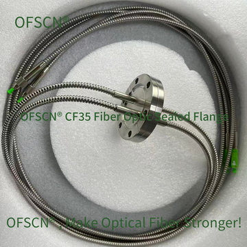
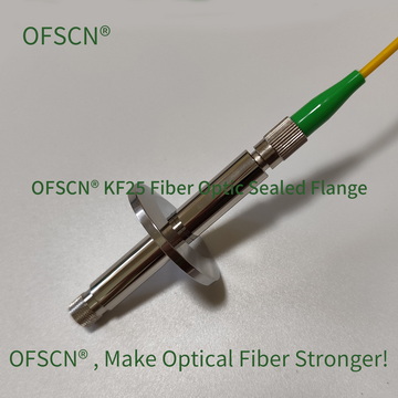
III. Official OFSCN® (DCYS) Vacuum Fiber Optic Flange Solutions
For demanding vacuum fiber optic coupling requirements in industrial and scientific research, Beijing Dacheng Yongsheng Technology Co., Ltd. (大成永盛) offers professional OFSCN® Fiber Optic Vacuum Sealed Flanges (大成永盛光纤真空密封法兰). These products perfectly integrate the aforementioned engineering error-proofing logic into their structural and material design:
- Series Support: Available in CF and KF series, offering single-channel, multi-channel, male, and female designs.
- High Vacuum Performance: Through high-precision machining and rigorous factory testing, the overall system achieves vacuum leak rates/vacuum levels better than 1 \times 10^{-7}\ \text{Pa} and 1 \times 10^{-9}\ \text{Pa}, respectively.
- Error-Proofing and Positioning: The CF series utilizes precision knife-edges and standard copper gasket recesses; the KF series employs a stainless steel centering ring structure, ensuring gaskets remain perfectly concentric during repeated assembly, disassembly, and sealing cycles.
- Temperature Adaptability: Standard versions operate at room temperature, with customizable options available for high-temperature resistance up to 250\ ^{\circ}\text{C}.
For product specifications and customization options, please refer to the official OFSCN® documentation:
OFSCN® Fiber Optic Vacuum Sealed Flange | Official Link
Below are standard product images for this series: