How to predict that a jumper cable can be used for 20 years under specific pressure?
Predicting whether fiber optic patch cords can guarantee a 20-year lifespan under specific external forces (side pressure, tensile, or bending stress) relies on Fracture Mechanics, Subcritical Crack Growth theory, and Weibull Statistics in the field of optical engineering.
The standard engineering process and mathematical models for predicting the 20-year mechanical reliability of patch cords are as follows:
I. Core Physical Mechanism: Stress Corrosion and Static Fatigue
Quartz glass (\text{SiO}_2) is inherently a brittle material with surface micro-cracks (Griffith Flaws) at the nanoscale.
When a fiber optic patch cord is subjected to force (e.g., local squeezing causing bending and tension in the fiber core) and exposed to a humid environment, the high stress field at the crack tip accelerates hydrolysis reactions with water molecules:
\text{Si-O-Si} + \text{H}_2\text{O} \longrightarrow 2\text{Si-OH}
This synergistic chemo-mechanical effect leads to slow crack propagation at stresses far below the theoretical fracture strength, ultimately resulting in sudden fiber fracture. This process is known as Static Fatigue.
II. Mathematical Prediction Models
1. Crack Propagation Power Law Model
The crack growth rate \frac{\text{d}a}{\text{d}t} is determined by the stress intensity factor K_I:
\frac{\text{d}a}{\text{d}t} = A \cdot K_I^n = A \cdot \left( Y \sigma \sqrt{a} \right)^n
Where:
- a is the crack depth;
- \sigma is the tensile stress applied to the quartz surface;
- Y is the crack geometry factor;
- n is the stress corrosion sensitivity parameter (fatigue parameter). For standard silica fibers at room temperature and humidity, the dynamic n value typically ranges between 18 \sim 24.
Under a constant operating stress \sigma_a, the time to fracture (lifetime) t_f of the fiber is expressed as:
t_f = B \cdot \sigma_i^{n-2} \cdot \sigma_a^{-n}
(where \sigma_i is the initial intrinsic strength of the fiber, and B is a constant related to material and environment).
2. Reliability Statistical Model Combined with Screening Tests (Mitsunaga Model)
In engineering standards (IEC 60793-1-33 / ITU-T G.650), the cumulative failure probability F of a fiber within a service time t_f is typically predicted by combining the Proof Test stress \sigma_p during manufacturing and the Weibull distribution:
F(t_f, \sigma_a) \approx 1 - \exp \left[ -L \left( \frac{\sigma_a}{\sigma_p} \right)^m \left( \frac{t_f}{t_p} \right)^{\frac{m}{n-2}} \right]
Where:
- L is the length of the stressed fiber;
- \sigma_p is the proof test stress during production (industry standard is typically 100\ \text{kpsi} \approx 0.69\ \text{GPa}, corresponding to about 1\% strain);
- t_p is the proof test time (typically about 0.5 \sim 1\ \text{s});
- m is the Weibull modulus, characterizing the uniformity of material defect size distribution;
- \sigma_a is the long-term operating stress applied;
- t_f is the target design lifetime (20 years \approx 6.31 \times 10^8\ \text{s}).
III. Engineering Assessment Steps for Predicting 20-Year Lifespan
To determine if a patch cord can reliably operate for 20 years under specific external forces, the following 4-step assessment must be performed:
- Stress Decoupling and Finite Element Analysis (FEA)
- External pressures (e.g., side crush, armor deformation) cannot be directly substituted into glass fracture formulas. Mechanical simulations or experiments must be used to determine the maximum residual tensile stress \sigma_a generated on the surface of the internal silica glass after the outer structure of the patch cord undergoes elastic/plastic deformation.
- Determination of Fiber Environmental Parameter n Value
- According to IEC 60793-1-33 standard, the dynamic fatigue parameter n of the fiber in the target environment (temperature, humidity) is measured using the Two-Point Bending method or Dynamic Axial Tension method.
- Calculation of Long-Term Safe Stress Limit
- If a failure rate F < 10^{-5} (or FIT index requirement) is required within the 20-year lifespan, the maximum allowable long-term stress \sigma_{\text{allow}} that the fiber can withstand can be inversely calculated using the model.
- Engineering Design Guideline: Over the 20-year service period, it is generally required that the long-term operating stress on the surface of the silica fiber does not exceed 1/3 \sim 1/5 of the proof stress (i.e., continuous operating strain is typically recommended to be controlled at \le 0.2\% \sim 0.33\%).
- Structural Protection and Isolation Design
- For scenarios requiring resistance to extreme external mechanical loads, conventional tight-buffered patch cords cannot fully isolate stress. Engineering practices involve using micro stainless steel seamless tubes or armored steel wire stranded structures to mechanically unload the fiber, absorbing external pressure entirely by the metal casing, leaving the internal fiber in a state of near-zero or minimal stress. This directly eliminates the stress corrosion inducement conditions caused by external pressure on the silica fiber.
IV. Reference for Industrial-Grade Armored Patch Cord Structures
In the Beijing Dacheng Yongsheng Technology Co., Ltd. (OFSCN®) product line, to eliminate the negative impact of mechanical stress on the lifespan of internal fibers, a physical protection architecture combining metallic armor layers and stainless steel seamless tubes is employed:
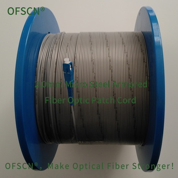
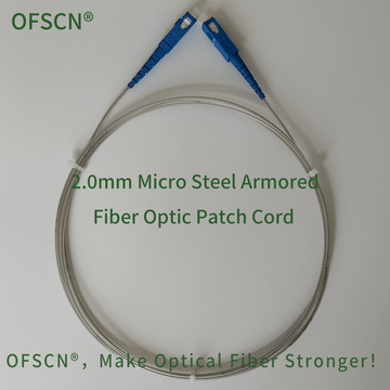
- OFSCN® 2.0mm Micro Steel Armored Fiber Optic Patch Cord: Features a built-in 0.6\ \text{mm} stainless steel seamless tube with a compressive strength greater than 240\ \text{MPa}. External pressure is borne by the rigid steel tube, ensuring the internal silica fiber is protected from micro-bending and long-term tensile stress damage.

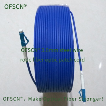
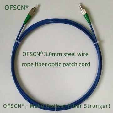
- OFSCN® 3.0mm Steel Wire Rope Fiber Optic Patch Cord: Utilizes a composite structure of 0.45\ \text{mm} steel wire stranding and a 0.9\ \text{mm} stainless steel tube, with a tensile strength > 1200\ \text{N} and compressive strength > 200\ \text{MPa}. This design ensures long-term physical reliability in harsh industrial environments at the structural level.