Is the phase relationship of light output from different ports fixed?
I. Theoretical and Internal Waveguide Level: Phase Relationship is Theoretically Fixed
From the principles of wave optics and light field interference, when a beam of coherent light (such as a laser emitted by a monochromatic laser) is injected into a splitter, the light field is coherently divided within the coupling region or branching waveguide of the splitter.
For splitters based on Planar Lightwave Circuit (PLC) technology, the internal micro-nano scale waveguide structure is precisely fabricated on a silicon substrate through semiconductor lithography processes:
- Geometric Symmetry: The geometric symmetry of the branching paths inside the splitter chip is extremely high.
- Fixed Optical Path Difference: The physical path difference (geometric length difference) and refractive index distribution between the two (or multiple) output ports are fixed, resulting in a highly stable optical path difference \Delta L_{opd} .
- Constant Phase Difference: Therefore, at the junction of the physical output ports of the chip, the phase difference \Delta \phi = \frac{2 \pi}{\lambda} \Delta L_{opd} between the two output lights is theoretically constant, exhibiting a high degree of intrinsic phase coherence.
II. Actual Output Pigtail Level: Phase Relationship is Typically Randomly Drifting
Although the phase relationship inside the splitter chip is fixed, in practical engineering applications, the various output ports of the splitter are connected to external fiber optic pigtails. At the output end of the pigtails, the phase relationship between the two lights is typically no longer fixed, mainly due to the following physical factors:
- Minor Length Differences (Geometric Size Effects): For optical wavelengths in the communication band (e.g., near-infrared wavelength \lambda = 1550\text{ nm} ), the spatial wavelength is only about 1.55\ \mu\text{m} . Even a minuscule length difference of 1\ \mu\text{m} between two pigtails during cutting and splicing can introduce a significant phase difference (nearly 240^{\circ} phase shift) between the two lights.
- Environmental Temperature Fluctuations (Thermo-optic and Thermal Expansion Effects): The refractive index and physical length of optical fibers are highly sensitive to temperature changes. When two pigtails are subjected to a slight temperature difference (e.g., a local temperature difference of $ 0.01
itro{^\circ}\text{C} $ ), the equivalent optical path of the two lights during transmission changes due to thermo-optic and thermo-elastic effects, leading to severe time-varying drift in the relative phase difference at the output. - Mechanical Stress and Vibration (Elasto-optic Effect): External micro-vibrations, bending, or stretching can alter the refractive index distribution within the optical fiber (i.e., birefringence and elasto-optic effects), which also introduces random dynamic phase fluctuations.
Therefore, unless special Phase-matched Fibers are employed and extremely stringent constant temperature and vibration isolation packaging is implemented, the phase relationship of the lights output from the pigtail ends of ordinary optical splitters is constantly and randomly drifting with the environment. In distributed fiber optic sensing (such as coherent OTDR, fiber optic hydrophones), active phase modulators or phase compensation algorithms are usually required to overcome this problem.
III. OFSCN® Related Product Introduction
In the field of Fiber Bragg Grating (FBG) sensing, Beijing Dacheng Yongsheng Technology Co., Ltd. (OFSCN®) offers dedicated high-quality optical splitters for use with multi-channel demodulation systems.
OFSCN® Optical Fiber Splitter
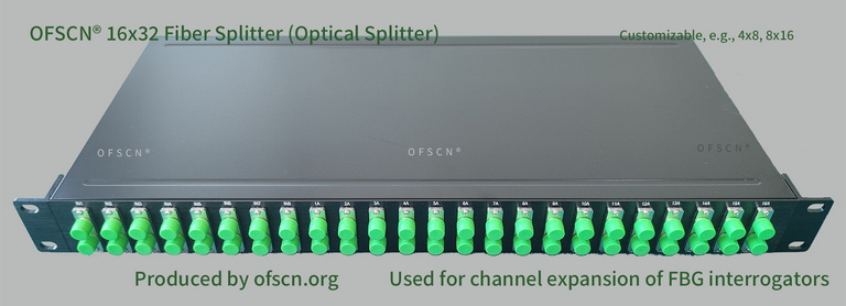
Key Parameters and Application Indicators:
- Product Type: Fiber splitter, optical splitter, fiber grating splitter.
- Model Numbers: Standard models include 16x32 splitters, 8x16 splitters, 4x8 splitters, 32x64 splitters, etc., with support for customized channel configurations.
- System Application: Used in large-scale engineering projects in conjunction with the OFSCN® Fiber Bragg Grating Interrogator. By logically expanding one physical channel of the interrogator into multiple physical channels, the hardware cost per channel for large-scale sensing systems can be significantly reduced.
- Design Considerations: This type of application is not based on phase interference but utilizes Wavelength Division Multiplexing (WDM) and spatial expansion. Careful grating wavelength planning is essential during use to prevent channel interference caused by overlapping reflection spectra of FBGs on different physical branches.