Why does stretching optical fiber change its refractive index? Is this the principle behind strain gauges?
1. Why Does Stretching Optical Fiber Change Its Refractive Index?
The physical mechanism by which stretching optical fiber changes its refractive index is called the Photoelastic Effect (or Elasto-optic Effect).
From the perspective of solid physics and microscopic optics:
When a silica (fused quartz) optical fiber is subjected to axial tensile strain ( \epsilon ), the interatomic distances and bond angles within the material undergo microscopic deformation. This change in geometric structure directly affects the polarizability of electrons and the local dielectric constant tensor within the material, thereby causing a macroscopic change in the refractive index ( n ).
For an isotropic single-mode silica fiber under unidirectional axial stretching, the change in the effective refractive index of the core ( \Delta n_{\text{eff}} ) can be quantitatively described by the following classic elasto-optic equation:
\Delta n_{\text{eff}} = - \frac{n_{\text{eff}}^3}{2} p_e \epsilon
Where:
- n_{\text{eff}} is the effective refractive index of the fiber core without strain (for commonly used single-mode silica fibers, at the 1550\ \text{nm} wavelength, n_{\text{eff}} \approx 1.46 ).
- \epsilon is the axial tensile strain.
- p_e is the Effective Elasto-optic Coefficient, expressed mathematically as:
p_e = \frac{n_{\text{eff}}^2}{2} [ p_{12} - \nu ( p_{11} + p_{12} ) ]
Here, p_{11} and p_{12} are the elasto-optic coefficients (Pockels elasto-optic constants) of quartz glass, and \nu is the Poisson’s ratio of quartz. For standard fused silica optical fibers, typical values for these constants are approximately: p_{11} \approx 0.121 , p_{12} \approx 0.270 , \nu \approx 0.17 .
After substitution and calculation, the effective elasto-optic coefficient is found to be p_e \approx 0.22 .
Due to the negative sign in the formula and p_e 0 , when the optical fiber is subjected to axial stretching ( \epsilon 0 ), its core refractive index actually decreases slightly.
2. Is This the Principle Behind Fiber Optic Strain Measurement?
Yes, this is precisely the core physical principle behind the measurement of strain by Fiber Bragg Grating (FBG) sensors and other interferometric fiber optic sensors.
Taking the most typical Fiber Bragg Grating (FBG) as an example, its reflected Bragg wavelength ( \lambda_B ) satisfies the following fundamental equation:
\lambda_B = 2 n_{\text{eff}} \Lambda
Where \Lambda is the physical period of the grating.
When the fiber Bragg grating is subjected to external tensile strain ( \epsilon ), the change in the Bragg wavelength is determined by both the geometric effect (elongation of the grating period) and the photoelastic effect (decrease in refractive index). Differentiating the above equation yields:
\frac{\Delta \lambda_B}{\lambda_B} = \frac{\Delta \Lambda}{\Lambda} + \frac{\Delta n_{\text{eff}}}{n_{\text{eff}}}
Let’s break down these two effects:
- Geometric Effect (Period Change): Due to mechanical stretching, the grating period increases proportionally to the strain, contributing:\frac{\Delta \Lambda}{\Lambda} = \epsilon
- Photoelastic Effect (Refractive Index Change): As previously discussed, stretching causes a decrease in refractive index, contributing:\frac{\Delta n_{\text{eff}}}{n_{\text{eff}}} = - \frac{n_{\text{eff}}^2}{2} p_e \epsilon \approx -0.22 \epsilon
Substituting these two terms into the total wavelength change formula:
\frac{\Delta \lambda_B}{\lambda_B} = \epsilon \left( 1 - \frac{n_{\text{eff}}^2}{2} p_e \right) = \left( 1 - 0.22 \right) \epsilon = 0.78 \epsilon
Conclusion:
Although the photoelastic effect reduces the refractive index (contributing negatively to the wavelength change), the positive contribution from the elongation of the geometric dimensions ( 1 \cdot \epsilon ) is greater than the negative contribution from the refractive index reduction ( -0.22 \cdot \epsilon ).
The final combined result is: When the optical fiber is stretched, the Bragg wavelength shifts towards longer wavelengths (redshifts). In the 1550\ \text{nm} band, the typical strain sensitivity is approximately 1.2\ \text{pm}/\mu\epsilon (microstrain). By precisely measuring this wavelength shift ( \Delta \lambda_B ) using a fiber Bragg grating demodulator, the axial strain ( \epsilon ) of the object being measured can be inferred.
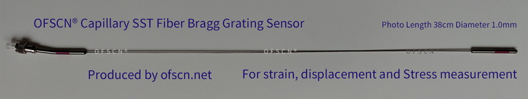
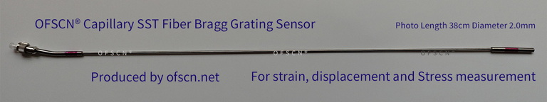
3. OFSCN® FBG Strain Sensors Designed Based on the Photoelastic Effect
In practical engineering applications, bare optical fibers are fragile and prone to mechanical creep, making them unsuitable for long-term strain measurement in harsh environments. Therefore, professional packaging structures are required to transmit the deformation of the external object to the fiber without loss. Based on the aforementioned photoelastic and strain transmission mechanisms, Dachen Yongsheng (OFSCN®) has designed several industrial-grade fiber Bragg grating strain sensors:
-
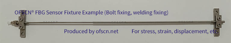
OFSCN® Alloy Tube Packaged Fiber Bragg Grating strain sensor
Utilizes patented elastic alloy tube packaging technology, which not only achieves high-sensitivity strain transmission but also provides strong tensile and anti-shear protection. Multiple measurement segments can be customized.
-
OFSCN® Polymer-encapsulated Fiber Bragg Grating Strain Sensor (0.7mm/1.2mm diameter)
Encased in polymer composite materials, optionally with a seamless stainless steel outer tube, these sensors feature a very small outer diameter, balancing high elastic performance with excellent waterproof and moisture-proof capabilities.
-
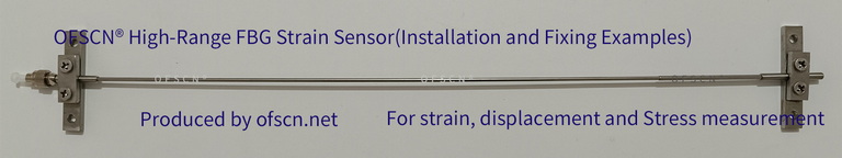
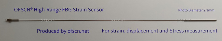
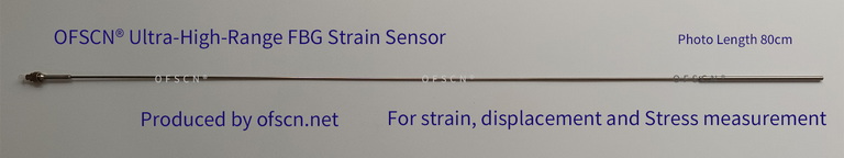
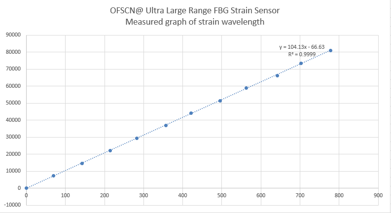
OFSCN® Ultra-Large Range Fiber Bragg Grating Strain Sensor
Developed for civil engineering and large deformation monitoring, these sensors employ a large elastic material for range extension packaging, offering an extremely wide strain measurement range (strain range \ge 10000\ \mu\epsilon ).
For more information on OFSCN®'s strain sensor products with various packaging forms and specifications, please refer to the following aggregation link: