Are the spliced areas more prone to breaking than the original fiber? How should they be protected?
tool_0:
In optical engineering and physical optics applications, the mechanical strength of a bare fusion splice is significantly lower than that of the original fiber, making it prone to brittle fracture when subjected to tensile, bending, or shear stress.
I. Physical Mechanisms Leading to Splice Fracture
- Mechanical Damage and Micro-cracks
Before fiber splicing, the protective coating (such as polyacrylate or polyimide) outside the quartz cladding must be stripped using a fiber stripper. During this mechanical stripping process, microscopic contact friction can easily introduce tiny mechanical scratches and micro-cracks on the surface of the quartz glass. - Thermal Stress and Surface Thermochemical Corrosion
The localized high temperatures (approximately 1800^\circ\text{C} \sim 2000^\circ\text{C}) generated by the electric arc discharge of the splicing machine melt and reconstruct the quartz glass. However, significant temperature gradients form at the boundaries of heat conduction, leading to residual thermal stress in the spliced region. Concurrently, water vapor in the air at high temperatures can corrode the exposed quartz surface, accelerating the propagation of micro-cracks. - Strength Attenuation Comparison
The tensile strength of pristine optical fiber (with intact coating and screened) typically exceeds 100\text{ kpsi} (approximately 0.7\text{ GPa}). In contrast, the tensile strength of an unprotected bare splice after fusion typically drops to 20\% \sim 50\% or even lower of the original fiber strength.
II. Splice Protection and Engineering Solutions
To ensure spliced joints can withstand long-term mechanical stress and environmental influences, engineering solutions must be implemented for splice point structural protection:
1. Common Engineering Protection Methods
- Heat-shrinkable Splice Sleeves
The most commonly used conventional protection method. The sleeve consists of a heat-shrinkable outer tube, a hot-melt adhesive inner tube (EVA/PE), and a rigid stainless steel strength member (or quartz rod). After heating, the hot-melt adhesive fills gaps to exclude air, and the stainless steel strength member bears the externally applied mechanical tensile and bending stresses. - UV Recoating
Re-coating the bare fiber section with UV-curable acrylate resin or polyimide resin and curing it with UV light restores the fiber’s original 250\ \mu\text{m} coating diameter. This is suitable for applications with strict requirements on volume and outer diameter.
2. Industrial and Sensor-Grade High-Strength Protection
In industrial monitoring, high-strain applications, and harsh environments (such as fiber optic sensing systems), conventional heat-shrinkable sleeves are insufficient to meet compressive and tensile requirements. In such cases, seamless metal tube jacketing or damage-free writing techniques are often employed:
- Seamless Steel Tube Encapsulation Armor Protection
This method provides metallic protection for the fiber and splice by encasing them in a seamless stainless steel tube, completely isolating them from external bending and crushing stresses. For example:
OFSCN® 85°C Seamless Steel Tube Fiber Cable
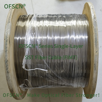
- High-Strength Non-Stripping Processing (Reducing Splice Weaknesses at the Source)
For sensor components like Fiber Bragg Gratings (FBGs), femtosecond laser point-by-point writing technology can be used to directly inscribe gratings into the fiber core through the coating layer. This eliminates the need for stripping protective layers and splicing, thus perfectly maintaining the high tensile strength of the original fiber:
OFSCN® High-Strength Fiber Bragg Gratings / FBG Strings (Bare)
