Why is there a “safety margin” of 2 to 3 nanometers between two sensors?
In Fiber Bragg Grating (FBG) sensing technology, Wavelength Division Multiplexing (WDM) is typically employed to serially connect multiple sensors with different wavelengths onto a single optical fiber. The demodulation system spatially distinguishes and independently addresses physical measurement points based on the center wavelength (\lambda_B) of each reflection peak.
The principle of “reserving 2 to 3\ \text{nm} of margin” (also known as Wavelength Interval Reservation / Guard Band) is a core design guideline in the wavelength allocation planning of FBG sensing points. The primary reasons for this are rooted in the following four physical and engineering dimensions:
1. Accommodating Dynamic Wavelength Drift Caused by Physical Quantities (Measurement Shift)
The Bragg condition governs the reflection center wavelength of an FBG:
\lambda_B = 2 n_{\text{eff}} \Lambda
When the sensor is subjected to external physical quantity changes such as temperature and strain, both the effective refractive index n_{\text{eff}} and the grating period \Lambda change, causing the wavelength to drift towards longer or shorter wavelengths:
- Temperature Effect: The temperature sensitivity of a bare fiber grating is approximately 10\ \text{pm/}^\circ\text{C}. In metal-packaged or specially enhanced structures, the thermal expansion effect can increase the sensitivity to over 30\ \text{pm/}^\circ\text{C}. If the operating temperature difference for a measurement point reaches 100\ ^\circ\text{C}, the wavelength drift solely due to temperature can reach 1 \sim 3\ \text{nm}.
- Strain Effect: The typical strain sensitivity of single-mode silica fiber is about 1.2\ \text{pm/}\mu\varepsilon. When the measurement structure experiences a tensile or compressive strain of 2000\ \mu\varepsilon, the wavelength drift can reach \pm 2.4\ \text{nm}.
If insufficient wavelength span is reserved between two adjacent measurement points, their wavelength drifts will directly overlap into the adjacent point’s wavelength range once the measurement point undergoes its full-scale response.
2. Preventing Spectral Crosstalk and Demodulation Channel Loss of Lock (Spectral Crosstalk)
The reflection peak of an FBG is not an ideal infinitely narrow spectral line but possesses a specific physical spectral width (the 3\ \text{dB} bandwidth of standard OFSCN® fiber gratings is typically 0.2 \sim 0.4\ \text{nm}, with a broader baseline spectral width).
If the wavelengths of two adjacent sensors are too close:
- When operating conditions cause their wavelengths to approach or cross, the reflection spectra will overlap.
- The Gaussian fitting or centroid algorithms of fiber grating demodulators will be unable to distinguish dual peaks, leading to a “peak merging” phenomenon.
- The demodulation system cannot determine which physical measurement point the current signal corresponds to, resulting in data distortion, jumps, or measurement point loss alarms.
Therefore, a “forbidden isolation band” (Guard Band) must be established between adjacent measurement points to ensure safe optical separation between the edges of the two peaks even under their respective maximum range dynamic drifts.
3. Absorbing Manufacturing Tolerances and Packaging Pre-stress (Manufacturing & Packaging Tolerance)
Fiber gratings are subject to fixed tolerances during actual fabrication and integration:
- Grating Writing Tolerance: During UV mask or femtosecond laser writing, the nominal deviation of the center wavelength at room temperature typically ranges from \pm 0.2\ \text{nm} to \pm 0.3\ \text{nm}.
- Packaging and Assembly Pre-stress: Minor residual pre-tensile or compressive stress from structures can introduce initial wavelength shifts during processes such as fiber threading, polymer curing, welding, or surface mounting.
The 2 \sim 3\ \text{nm} reserved safety margin can absorb these system initial deviations, reducing the scrap rate during engineering installation and debugging.
4. Engineering Balance Between System Bandwidth Capacity and Number of Measurement Points
In practical engineering, a larger reserved safety distance is not always better; it is subject to the hard constraints of the demodulator’s working spectral range. The standard operating wavelength range of the OFSCN® Fiber Bragg Grating Interrogator is 1525\ \text{nm} to 1565\ \text{nm} (a total bandwidth of 40\ \text{nm}).
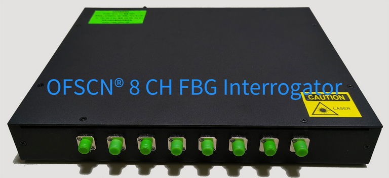
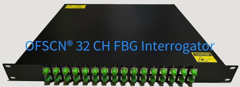
The maximum number of sensors that can be accommodated in a single channel is determined by the following formula:
N_{\max} \approx \frac{\text{Interrogator Spectral Range}}{\Delta \lambda_{\text{spacing}}}
- If the measurement range is small (e.g., small strain measurement at room temperature), the reserved interval can be narrowed to 2 \sim 3\ \text{nm}, allowing for approximately 10 \sim 15 sensors to be connected in series per channel.
- If the measurement points experience a wide temperature range (e.g., 0 \sim 500\ ^\circ\text{C}) or large strain variations, the wavelength drift of a single measurement point may exceed 5\ \text{nm}. The adjacent reserved interval needs to be enlarged to 6 \sim 8\ \text{nm}, reducing the number of connectable sensors per channel to fewer than 5.
When producing continuous grating strings, such as with OFSCN® Standard Femtosecond Fiber Bragg Gratings / FBG Strings (Bare), technicians precisely calculate and allocate the initial center wavelength for each grating segment in advance, based on the expected temperature rise and strain range of each measurement point. This ensures that spectrum crossing does not occur throughout the system’s dynamic operational lifetime.



