If the coating is too tight, will it deform the glass inside?
From the perspectives of optical engineering and solid mechanics principles: an overly tight fiber coating or tight buffer indeed imposes mechanical stress and causes elastic deformation on the internal silica glass, but within the normal operating stress range, this deformation is elastic, not plastic (permanent).
I. Physical Mechanisms and Material Mechanics Analysis
-
Material Elasticity and Compressive Properties
The primary component of standard quartz optical fiber cores and cladding (typically 125\ \mu\text{m} cladding outer diameter) is silicon dioxide (\text{SiO}_2), which has a high Young’s modulus (E \approx 72\ \text{GPa}) and an extremely high compressive strength (exceeding 1\ \text{GPa}). Polymer coatings (such as polyacrylate, polyimide, etc.), when curing shrinkage or environmental temperature changes occur, exert a radial inward compressive stress \sigma on the glass cladding due to their far greater coefficient of thermal expansion than glass (\alpha_{\text{polymer}} \gg \alpha_{\text{glass}}). -
Microbending Loss
When the radial stress exerted by the coating is uneven, or when the tight buffer material shrinks too strongly during curing, the compressive force can cause micro-level physical bending (i.e., microbending) in the glass fiber. This slight deformation disrupts the total internal reflection condition for guided modes, causing light from the core to leak into the cladding, manifesting as additional attenuation of the optical signal due to microbending. -
Photoelastic Effect and Birefringence
Even with very slight physical deformation of the glass (microstrain), the anisotropic stress field generated by asymmetric compression can alter the local refractive index of the silicon dioxide material through the photoelastic effect, inducing stress birefringence. This can increase polarization mode dispersion (PMD) or cause splitting or broadening of the reflection spectral peaks in Fiber Bragg Gratings (FBGs).
II. Engineering Countermeasures and Encapsulation Design
In the design of fiber optic sensors and transmission lines, engineering approaches to handle coating stress are primarily divided into the following categories:
- High Modulus Thin Coating Control
To avoid asymmetric stress from thick coating shrinkage, especially in applications requiring high temperatures or precise strain transfer, extremely thin coatings with strong adhesion are often used. For example, the OFSCN® 300℃ SM Polyimide Optical Fiber, with a cladding outer diameter of 125\ \mu\text{m}, has a polyimide coating with an outer diameter of only 155\ \mu\text{m}. This thin coating can uniformly transmit mechanical states and prevent non-uniform squeezing of the glass by coating creep.


- Controlled Stress/Strain Transfer
In the field of strain and stress sensing, the precise transfer of strain from the substrate to the fiber core (in accordance with the \sigma = E \cdot \epsilon relationship) is achieved through the tight integration of encapsulation materials with the glass fiber. For example, the OFSCN® Alloy Tube Packaged Fiber Bragg Grating strain sensor and OFSCN® Fiber Bragg Grating Stress Sensor utilize seamless elastic alloy tubes and proprietary encapsulation techniques to ensure the glass fiber operates under controlled tension and compression.


- Stress-Free Suspended Decoupling Design
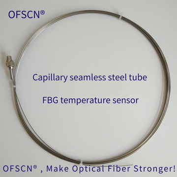
If the goal is precise temperature measurement, it is essential to completely eliminate any compressive stress exerted by the coating and protective tube on the glass fiber. For instance, the OFSCN® 100°C Fiber Bragg Grating Temperature Sensor employs a seamless steel tube, stress-free suspension encapsulation technique. The optical fiber is placed inside the metal protective tube, allowing it to expand and contract freely with temperature changes, thus completely isolating it from cross-interference caused by external structures and coating compression.