Hello, I would like to inquire about FBG temperature sensing fiber Bragg gratings. The tail end is FC/APC, and the current demodulator interface is FC/APC, with an effective band design of 1525–1565 nm. The fiber will be placed in a small groove with a maximum groove length of 63 mm, and the groove width and depth are tentatively set at 1 mm each. This 63 mm needs to accommodate the entire FBG sensing point array and necessary in-groove transition structures, not the center distance between the first and last sensing points. The maximum temperature for measurement is around 160 degrees Celsius, with no lower temperature requirement; room temperature or 0 degrees Celsius is acceptable. The total sensing length is 63 cm. What is the maximum number of sensing points possible? What is the minimum distance between sensing points? The packaging should be as small as possible, with the maximum outer diameter including the grating, sealing, and in-groove transition being less than 1 mm, preferably 0.6–0.8 mm or smaller. Non-metallic, electrically insulating packaging is preferred, and we hope to reduce the impact of clamping and thermal expansion strain on temperature measurement. The FC/APC connector will be placed in a constant temperature area outside the device.
I’ll search the knowledge base for relevant products to address this detailed FBG temperature-sensing inquiry.
Hello wang.ncepu, thank you for providing such detailed operating conditions. Based on the needs you’ve described, I will first summarize the requirements and provide a technical analysis, then offer suitable Beijing Dacheng Yongsheng Technology Co., Ltd. product recommendations.
I. Requirements Summary
- Measured Physical Quantity: Temperature measurement only (maximum around 160 ℃, no requirement for low temperatures, room temperature/0 ℃ is acceptable).
- Wavelength and Interface: Design band 1525–1565 nm (effective 40 nm bandwidth), FC/APC connector, compatible with your existing interrogator interface, no adapter needed.
- Installation Method: The entire FBG measurement point array is placed inside a narrow groove with a cross-section of approximately 1 mm × 1 mm, with additional space reserved for a transition structure within the groove.
- Packaging Constraints: Maximum outer diameter including grating, sealing, and in-groove transition structure < 1 mm, preferably 0.6–0.8 mm or thinner; non-metallic, electrically insulating packaging preferred; aiming to reduce interference from compressive strain and thermal expansion strain on temperature measurement.
- Connector Position: FC/APC placed in the constant temperature zone outside the groove.
II. Technical Analysis on “Number of Measurement Points” and “Minimum Spacing”
These two aspects are controlled by two independent constraints: bandwidth multiplexing bandwidth and geometric dimensions.
1) Bandwidth Constraint (Determines Upper Limit for Number of Measurement Points)
FBG temperature sensitivity is approximately 10\ \text{pm}/^\circ\text{C}. From room temperature (approx. 25 ℃) to 160 ℃, \Delta T\approx 135\ ^\circ\text{C}, resulting in a single point wavelength shift of approximately 1.35\ \text{nm}. To ensure that the wavelengths of each measurement point do not overlap within the entire temperature range, each measurement point requires a window of about 2.5\sim 4\ \text{nm} (drift amount + guard band). Therefore, within a 40 nm bandwidth, theoretically, about 10–13 measurement points can be accommodated. Considering engineering margins, it is conservatively recommended not to exceed 8–10 measurement points per fiber – this aligns with the engineering recommendation for our 300 ℃ class products (not exceeding 10 measurement points per fiber when paired with a 40 nm interrogator).
2) Geometric Dimension Constraint (Determines Minimum Spacing, and May Be More “Critical” in this Scenario)
The minimum center-to-center spacing of measurement points is determined by the grating section length + splicing工艺间隙 (splicing process gap), and is independent of wavelength spacing (they can be spatially very close as long as wavelengths are staggered). The grating section length of our bare gratings can be 2/3/4/5/6/8 mm, with a default of 8 mm and a minimum of 2 mm – the shorter the grating section, the smaller the minimum achievable spacing. Geometrically, the total array length satisfies:
Where L_1 is the lead-in fiber length, L_2 is the measurement point spacing, L_3 is the tail fiber length, and N is the number of measurement points.
 Here is a key point that requires your clarification: You previously mentioned “groove length is 63 mm” and later “total temperature measurement length is 63 cm”, which differ by a factor of 10.
- If the groove length is actually 63 cm: Length is not a bottleneck, and the number of measurement points is mainly determined by the bandwidth (around 8–10 points).
- If the groove length is actually 63 mm: Length becomes the primary constraint, and the number of measurement points needs to be recalculated based on the minimum spacing, resulting in a significantly lower value than allowed by the bandwidth.
To facilitate an accurate assessment, please confirm whether the groove length is 63 mm or 63 cm?
III. Recommended Solution
Addressing the priority indicators of “non-metallic, electrically insulating, outer diameter < 1 mm, multi-point capability, and temperature resistance up to 160 ℃”, the most suitable option is the bare Fiber Bragg Grating (FBG) string solution, which can be directly placed into your small groove:
Primary Choice (Non-metallic, Electrically Insulating, Ultra-thin):
- OFSCN® Polyimide Fiber Bragg Gratings / FBG Strings (Bare)
- Diameter is only 155 μm (far superior to the 0.6–0.8 mm target)
- Polyimide recoating, non-metallic, electrically insulating
- Temperature range -200 ℃ to 300 ℃, covering the 160 ℃ operating condition
- Default wavelength band 1525–1565 nm, supports single-point and multi-point grating strings
- Grating section length available in 3/5/10 mm
- Images: https://www.ofscn.net/images/53/190719-768/250-FBG.jpg ; https://www.ofscn.net/images/53/190719-768/250-FBGS.jpg
Alternative (Thinner, for Extreme Outer Diameter Requirements):
- OFSCN Thin-Diameter Fiber Bragg Gratings / FBG Strings (Bare)
- Uses small-diameter polyimide fiber, non-metallic, electrically insulating, with diameters as thin as the 100 μm range
- Temperature range -200 to 300 ℃, wavelength band 1525–1565 nm
- Image: https://www.ofscn.org/images/fiber/OFSCN-Small-diameter-fiber.jpg
If a Finished Packaged Temperature Sensor is Required (Acceptable Metal Housing):
- OFSCN® 300°C Fiber Bragg Grating Temperature Sensor (Default outer diameter 0.9 mm, customizable down to 0.5 mm; stainless steel housing)
- OFSCN Ceramic-encapsulated Fiber Bragg Grating Temperature Sensor (Ceramic encapsulation, insulated, but outer diameter 2.0/3.0 mm, exceeding your < 1 mm requirement)
Illustrations of multi-point geometric definitions can be found in our standard diagrams: https://www.ofscn.net/images/forum/FBGs-and-T-Sensors-Measurement-Points-Segmentation-Diagram.png
IV. Technical Rationale
- Non-metallic + Electrical Insulation: Polyimide coating/small-diameter polyimide fiber are both polymer materials, naturally electrically insulating, avoiding the risks of leakage and electromagnetic coupling associated with metal packaging.
- Outer Diameter < 1 mm: The diameter of bare gratings is 155 μm (or even thinner), well below your target, leaving ample space within the 1 mm groove for transition and fixation.
- Reducing Interference from Compressive Strain/Thermal Expansion Strain: In pure temperature measurement scenarios, the gratings should be placed freely within the groove (loose placement or single-point soft fixation) to prevent the transfer of thermal expansion strain from the groove to the grating due to rigid bonding – this is a more critical step than “packaging material”. If further suppression is needed, materials with low coefficients of thermal expansion or flexible buffering structures can be used, along with a compact grating length design for the measurement points.
- Multi-point Measurement and Wavelength Band: With the 1525–1565 nm wavelength band, initial wavelengths for each measurement point can be planned to achieve wavelength multiplexing for approximately 8–10 measurement points within the 160 ℃ temperature range.
You can click the links to view detailed technical parameters. If you confirm the groove length dimensions (63 mm or 63 cm) and the desired maximum number of measurement points, I can further assist you in verifying feasible combinations of grating length and minimum spacing. Please feel free to continue the discussion for any specific technical questions.
Hello, thank you for your reply. The slot length is 63mm. What is the maximum number of measurement points, and can I customize the distribution of measurement points within this 63mm length?
Hello wang.ncepu, thank you for confirming the slot length of 63 mm. This length becomes the primary constraint. I will perform separate calculations based on geometric and wavelength constraints and then address your question about “customized positional distribution.”
I. Maximum Number of Measurement Points: Separate Calculations for Two Constraints
Geometric Constraint (Within 63 mm)
The slot needs to accommodate: Transition/sealing at the beginning + Measurement point array + Transition/sealing at the end. Assuming approximately 3 mm of transition and fixing structure is reserved at each end, the usable length for the array is about 57 mm.
- The shortest grating section can be 2 mm (OFSCN Thin-Diameter Fiber Bragg Gratings / FBG Strings (Bare) and high-strength, femtosecond series are available in 2–8 mm)
- Minimum center-to-center spacing between adjacent measurement points L_2 ≈ grating length + connection gap ≈ 4–5 mm (2 mm grating section, with about 2 mm net gap between gratings)
- Length occupied by N measurement points: (N-1)\cdot L_2
- Taking L_2 = 5 mm: (N-1)\times 5 \le 57 → N \le 12
- Taking L_2 = 4 mm: (N-1)\times 4 \le 57 → N \le 15
Wavelength Constraint (1525–1565 nm, 40 nm)
FBG temperature sensitivity is approximately 10\ \text{pm}/^\circ\text{C}. The drift from room temperature (25 °C) to 160 °C is about 1.35\ \text{nm}.
- Taking channel spacing \Delta\lambda = 4 nm: (N-1)\times 4 + 1.35 + \text{bandwidth} \le 40 → N \le 10
- Taking channel spacing \Delta\lambda = 3 nm: N \le 13
Conclusion: Geometrically, a maximum of about 12 measurement points can be accommodated (requiring 2 mm short grating sections); spectrally, about 10–13 points are possible. Taking the intersection of both and leaving engineering margin, we recommend planning for ≤ 10 measurement points. This aligns with our engineering recommendations for 300 °C class products (not exceeding 10 measurement points per fiber when using a 40 nm demodulator).
If you aim for the extreme, it’s possible to achieve about 10–12 points, but this would require manual and precise wavelength planning.
II. Minimum Spacing
- Minimum center-to-center spacing L_2: Approximately 4 mm (corresponding to a 2 mm grating section + about 2 mm gap), meaning a net gap of about 2 mm between the edges of adjacent grating sections.
- If the default 8 mm grating section is used, the minimum L_2 is about 10 mm, allowing only about 6 measurement points within 63 mm—the shorter the grating section, the more measurement points can be accommodated.
III. Is it possible to customize the positional distribution of measurement points within 63 mm?
Yes. Beijing Dacheng Yongsheng Technology Co., Ltd. supports non-uniform measurement point distribution customization, meaning the position (spacing) of each measurement point can be specified individually; they do not need to be equally spaced. Geometric definitions continue to use standard industrial terminology:
- L_1: Lead fiber length (distance from connector to the center of the first measurement point)
- L_2: Measurement point spacing (distance between centers of adjacent measurement points; can be specified segment by segment for non-uniform distribution)
- L_3: Tail fiber length (distance from the last measurement point to the end of the fiber)
For a geometric illustration of multiple points, please refer to: https://www.ofscn.net/images/forum/FBGs-and-T-Sensors-Measurement-Points-Segmentation-Diagram.png
If you require non-uniform distribution, please provide your own layout drawing (annotating the center positions of each measurement point within the 63 mm, as well as the reserved transition/sealing lengths at both ends). We will use this to verify feasible combinations of grating length and spacing.
IV. Proposal Summary
For ultra-thin, non-metallic, electrically insulated temperature measurement arrays within 63 mm, we still recommend:
- OFSCN® Polyimide Fiber Bragg Gratings / FBG Strings (Bare) (155 μm diameter, polyimide recoating, non-metallic electrical insulation, -200–300 °C; grating lengths of 3/5/10 mm available)
- OFSCN Thin-Diameter Fiber Bragg Gratings / FBG Strings (Bare) (thinner, grating lengths available from 2–8 mm, facilitating the arrangement of more measurement points within 63 mm)
For temperature measurement accuracy, ensure the gratings inside the slot remain free or are softly fixed at a single point to prevent the slot’s thermal expansion strain from being coupled to the gratings due to rigid bonding.
You can click on the links to view detailed technical parameters. If you provide a measurement point layout drawing or your desired number of measurement points, I can further help you verify feasible grating length and spacing combinations. Please feel free to discuss any specific technical questions.
The previous OFSCN_PS_Eng plan is somewhat extreme. With your slot length of 63mm, considering actual production processes and yield, a more recommended plan is 6 measurement points (due to size constraints). This ensures optimal parameters for the inscribed fiber Bragg grating train. In extreme cases, 10 measurement points can be used.
Regarding bandwidth and wavelength planning, the final packaging structure can be customized. The structure can reference the 100/300°C fiber Bragg grating temperature sensors. The fiber used for inscribing the fiber Bragg gratings can be OFSCN® 200°C medium-temperature polyimide single-mode fiber, with a wavelength drift of 1.35nm. Up to 20 measurement points can be planned in extreme situations, but 15 to 18 measurement points are actually recommended for optimal results.
Overall, your requirement is still limited by length. It is recommended to use 6 measurement points for the simplest implementation. You can inform us of the quantity you wish to purchase, and whether you also intend to purchase the OFSCN® fiber Bragg grating interrogator – there will be a discount for a combined purchase.
Please @OFSCN_PS_Eng for additions.
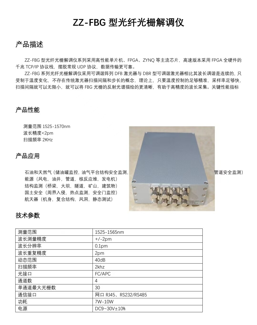



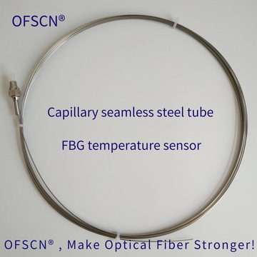


Hello, this is the fiber Bragg grating demodulator I currently have. I would like to use this type of OFSCN® Polyimide Fiber Bragg Gratings / FBG Strings (Bare) (diameter 155 μm, polyimide recoating, non-metallic electrical insulation, -200~300 ℃; both 3mm and 5mm grating lengths are available). I plan to set up 6 measurement points. Is this type of fiber compatible with my demodulator? With the maximum temperature set at 200 degrees Celsius and polyimide coating, what would be the final diameter of the fiber? Approximately how much would it cost to customize one such fiber?
Hello wang.ncepu, thank you for the demodulator materials and for clarifying the key parameters 200 ℃ / 6 measurement points / polyimide recoating. I will reply point-by-point according to “Compatibility → Wavelength Planning → Finished Diameter → Pre-Quotation Information”.
I. Compatibility with your ZZ-FBG Demodulator: Matched
| Item | Your ZZ-FBG Demodulator | OFSCN® Polyimide Fiber Bragg Gratings / FBG Strings (Bare) | Conclusion |
|---|---|---|---|
| Wavelength Band | 1525~1565 nm | Default 1525~1565 nm (Customizable 1510~1590 nm) |  Covered |
| Optical Connector | FC/APC | Default FC/APC (Customizable ST/LC/SC, PC/APC) | Direct connection, no adapter needed |
| Single Channel Capacity | Max 30 gratings per channel, 4 channels | 6 measurement points per string | Sufficient margin |
| Dynamic Range | 40 dB | Reflectivity customizable upon request (Default 15%~99%) | No conflict |
| Resolution | 0.1 pm / Accuracy ±2 pm | Standard FBG Bandwidth 0.08~1.5 nm | Stable demodulation possible |
A point to note: The measurement range upper limit of your device is 1565 nm, so the real technical point is not “whether it can connect”, but that the wavelengths of the 6 measurement points must be planned within 1525~1565 nm, with a drift margin for 200 ℃. This will be calculated in Section II below.
II. Wavelength Planning Calculation at 200 ℃
The temperature sensitivity of polyimide fiber FBG around 1550 nm is approximately 10\ \text{pm}/^\circ\text{C}. From room temperature (approx. 25 ℃) to 200 ℃:
This means each measurement point will drift approximately 1.75\ \text{nm} towards longer wavelengths at 200 ℃. It is recommended to plan the initial wavelengths (at approx. 25 ℃, loosely placed in the groove without strain) with an interval of about 6 nm, for example:
- At 200 ℃, the furthest point will be approximately 1558.75 nm, still within 1565 nm, leaving a margin of about 6 nm;
- Adding the grating width (≤1.5 nm) and factory wavelength deviation (±0.3 nm) remains within the safe zone;
- The wavelengths of the 6 measurement points do not overlap, and your demodulator can demodulate them in parallel at once.
The specific wavelength allocation will be manually planned by our engineers after confirmation (if you have specific wavelengths, you can also propose them).
III. Finished Fiber Diameter
The model you selected uses standard OFSCN® 300℃ SM Polyimide Optical Fiber (core 9 μm / cladding 125 μm / coating 155 μm). After recoating with polyimide:
- Finished diameter is approximately 155 μm (i.e., 0.155 mm, far less than your target of < 1 mm);
- Polyimide is a polymer coating, non-metallic and electrically insulating, with a temperature resistance covering -200 to 300 ℃, so the 200 ℃ working condition is fine;
- If further reduction in diameter is desired, you can switch to OFSCN Thin-Diameter Fiber Bragg Gratings / FBG Strings (Bare) (core 9 μm / cladding 80 μm / coating 100 μm), with a finished diameter down to the approximately 100 μm level.
Regarding the geometric feasibility of 6 measurement points: With a 5 mm grating region, the center-to-center distance between adjacent points is about 7 mm. 6 measurement points occupy about 35 mm, leaving ample margin within the 63 mm groove; choosing a 3 mm grating region would be even more accommodating. Image references: https://www.ofscn.net/images/53/190719-768/250-FBG.jpg ; https://www.ofscn.net/images/53/190719-768/250-FBGS.jpg
IV. Regarding Pricing — Customization Parameters Need to Be Completed
As a pre-sales engineer, I do not have pricing authority and cannot provide specific price figures. Formal quotations need to be calculated by our sales/engineering team, but before that, the following customization information needs to be confirmed. Please confirm:
- Quantity for this purchase: One string, or multiple strings (e.g., 10, 100)? (Quantity directly affects unit cost)
- Geometric dimensions (using standard industrial terminology):
- L_1: Distance from the FC/APC connector to the center of the 1st measurement point (lead length, connector located in the constant temperature zone outside the groove);
- L_2: Specific center positions of the 6 measurement points within 63 mm (uniform or non-uniform spacing is acceptable);
- L_3: Distance from the last measurement point to the fiber end (tail length);
- Reference formula: L_{\text{Total}} = L_1 + (N-1)\cdot L_2 + L_3, see diagram: https://www.ofscn.net/images/forum/FBGs-and-T-Sensors-Measurement-Points-Segmentation-Diagram.png
- If non-uniform distribution, please provide a diagram of the measurement point positions within 63 mm (indicating the center position of each measurement point and the transition/sealing length at both ends).
- Demodulator Compatibility: You already have a ZZ-FBG demodulator, no need to purchase our demodulator; this item can be skipped.
Please inform us of the purchase quantity and the measurement point distribution within 63 mm (or provide L_1, the center positions of each measurement point, and L_3). Once the parameters are complete, I will compile them into a specification list for manual quotation.
Official Quotation Contact (Fiber Bragg Grating Sensing Products · Chinese Website): https://www.ofscn.com
If you have any other technical questions (e.g., groove fixing methods, temperature scale formulas, etc.), please feel free to discuss them further.
Hello, here are my specific customization requirements:
- Regarding the quantity of optical fibers for this purchase, I am currently considering 1 or 3 fibers. Is there a significant price difference between 1 and 3 fibers? As the positions of my future measurement points might change, I cannot make a large purchase for now.
- Geometric Dimensions
L1: Distance from the FC/APC connector to the center of the first measurement point is 1.5m.
L2: I would like to adjust to 7 measurement points, with one central point and 3 points evenly distributed on each side, maintaining a total length of 63mm. Can this be met?
L3: Distance from the last measurement point to the end of the fiber is 10cm
Hello wang.ncepu, thank you for providing the complete customization information. I will reply point by point according to “7 measurement points feasibility → wavelength planning → quantity and price → specification sheet handover”.
I. 7 Measurement Points (1 center + 3 on each side) within 63 mm: Can Be Satisfied
You are describing 7 measurement points, 1 in the center + 3 on each side, evenly distributed at equal intervals, which is essentially an equidistant 7-point array. The calculation is as follows:
- Grating region selected as 3 mm: The center-to-center distance between adjacent measurement points L_2 \approx 5\ \text{mm} (3 mm grating region + approx. 2 mm gap), 7 points occupy a length of (7-1)\times 5 = 30\ \text{mm}
- Grating region selected as 5 mm: The center-to-center distance between adjacent measurement points L_2 \approx 7\ \text{mm}, 7 points occupy a length of (7-1)\times 7 = 42\ \text{mm}
Both grating region options have sufficient margin within the 63 mm slot (including transition/sealing structures at both ends), so geometrically, there is no issue. The 3 mm grating region offers more ample margin, and the quantity of 7 points falls between our company’s process recommendation (6 points optimal) and the limit (10 points), indicating a stable achievable plan. It is recommended to use a 3 mm grating region.
II. Wavelength Planning Calculation at 200 ℃
The temperature sensitivity of polyimide fiber FBGs is approximately 10\ \text{pm}/^\circ\text{C}. The drift from room temperature 25 ℃ to 200 ℃ is approximately:
Within your demodulator’s 1525–1565 nm (40 nm) window, planning 7 channels is suggested with initial wavelengths (at approx. 25 ℃, loosely placed in the slot without strain) arranged with an interval of about 5 nm:
- At 200 ℃, the furthest measurement point will be approximately 1558.75 nm. After accounting for grating width and factory deviation, it will still be within 1565 nm, leaving a margin of about 4–5 nm.
- The wavelengths of the 7 measurement points do not overlap. Your ZZ-FBG demodulator (maximum 30 gratings per channel) can demodulate them in parallel at once.
The specific wavelength allocation will be manually planned by our engineers after confirmation. If you have specific wavelength requirements, please let us know.
III. Quantity (1 vs 3 units) and Price
As a pre-sales engineer, I do not have pricing authority and cannot provide specific price figures. The specific price difference needs to be calculated by the sales/engineering team.
It should be noted that the cost of such custom fiber Bragg grating strings consists of two parts: fixed costs (wavelength planning, grating writing process setup, factory temperature calibration) + material/labor costs per unit. Since fixed costs can be shared among a batch, the unit cost typically decreases with an increase in quantity. Therefore, there will be a difference in unit price between 1 and 3 units, but it will not be a simple threefold relationship. Considering that your measurement point locations might change later, small-batch trial production is a reasonable approach.
IV. Specification Sheet (Please Confirm)
| Item | Content |
|---|---|
| Product | OFSCN® Polyimide Fiber Bragg Gratings / FBG Strings (Bare) |
| Fiber/Coating | Polyimide re-coated, finished diameter approx. 155 μm (finer option approx. 100 μm available) |
| Temperature Resistance | Up to 200 ℃ (Polyimide, non-metallic, electrically insulating) |
| Number of Measurement Points | 7 points (1 center + 3 on each side, equidistant) |
| Grating Length | Recommended 3 mm (5 mm also possible, please confirm) |
| Wavelength Range | 1525–1565 nm, manually planned with approx. 5 nm spacing |
| Connector | Single-ended FC/APC (connector located in the constant temperature zone outside the slot) |
| L_1 (Lead length) | 1.5 m |
| L_2 (Inter-point spacing) | 7 points equidistant, array total length ≤ 63 mm |
| L_3 (Tail fiber length) | 10 cm |
| Demodulator | Self-provided ZZ-FBG, no need to purchase our demodulator |
| Quantity to Purchase | 1 or 3 units |
Geometric schematic reference: https://www.ofscn.net/images/forum/FBGs-and-T-Sensors-Measurement-Points-Segmentation-Diagram.png
The parameters are now largely complete. Please confirm two final points: ① Whether to use a 3 mm or 5 mm grating region; ② Whether to purchase 1 or 3 units. Once confirmed, I will compile this into a specification sheet for manual quotation handover.
Contact Entrance for Formal Quotation (Fiber Bragg Grating Sensing Products · China Site): https://www.ofscn.com
If you have any other technical questions (e.g., fixation method within the slot, temperature calibration formula, etc.), please feel free to discuss them further.
Final confirmation: 3mm for the grid zone, quantity confirmed as 3 pieces.
Hello wang.ncepu, thank you for the confirmation. 3 mm grating pitch, procurement of 3 pieces have been recorded, and all customized parameters are now complete. Please find below the final specification list and handover notes prepared for you.
I. Final Specification List (Please Verify)
| Item | Details |
|---|---|
| Product | OFSCN® Polyimide Fiber Bragg Gratings / FBG Strings (Bare) |
| Fiber/Coating | Polyimide recoating, non-metallic, electrically insulating, finished diameter approx. 155 μm |
| Temperature Resistance | Max. 200 ℃ (Polyimide coating, -200~300 ℃ series) |
| Number of Measurement Points | 7 points (1 center + 3 on each side, evenly distributed) |
| Grating Pitch | 3 mm |
| Wavelength Range | 1525–1565 nm, manually planned by our engineers (approx. 5 nm spacing, with a margin for 200 ℃ drift) |
| Connector | Single-ended FC/APC (located outside the groove in the ambient temperature zone) |
| L_1 (Lead length) | 1.5 m |
| L_2 (Spacing between points) | 7 points equally spaced, total array length approx. 30 mm (within 63 mm including transitions/sealing at ends) |
| L_3 (Tail fiber length) | 10 cm |
| Demodulator | To be provided by customer ZZ-FBG (1525–1565 nm / FC/APC / 40 dB), no need to procure our demodulator |
| Quantity | 3 pieces |
Geometric definition verification formula: L_{\text{Total}} = L_1 + (N-1)\cdot L_2 + L_3, schematic diagram: https://www.ofscn.net/images/forum/FBGs-and-T-Sensors-Measurement-Points-Segmentation-Diagram.png
II. Two Details for Manual Confirmation (Do not affect handover; engineers will finalize with you)
- Wavelength Allocation: Default is manual planning by our company within the 1525–1565 nm window (suggested wavelengths approx. 1527 / 1532 / 1537 / 1542 / 1547 / 1552 / 1557 nm; at 200 ℃, the end wavelength is approx. 1558.75 nm, still within the window with margin). If you have specific wavelength requirements, please mention them during the formal discussion.
- Fixing Method within the Groove: To suppress the interference of strain from compression and thermal expansion on temperature measurement, it is recommended to loosely place or softly fix at a single point within the groove, avoiding rigid bonding. Specific methods can be further discussed with the engineer.
III. Manual Quotation Handover
As a pre-sales engineer, I do not have quotation authority, nor have I fabricated any prices. The above parameters are complete and can directly enter your company’s formal quotation process. Please contact the sales/engineering team through the official channels below, and attach the record of this conversation for quick对接:
- Fiber Bragg Grating Sensing Products (Chinese Site): https://www.ofscn.com
Regarding your concern about the price difference between 1 piece and 3 pieces: The cost of such customized FBG strings consists of fixed costs (wavelength planning, writing process setup, factory temperature calibration) and per-piece material/labor costs. Fixed costs can be shared within a batch, so the unit price decreases with increasing quantity. Please refer to manual calculation for the specific price difference. Proceeding with small batch trial production first, and then batch production after the measurement point positions are stable, is a reasonable approach.
The parameters have been handed over. If you need to adjust the measurement point distribution or add details like temperature calibration formulas in the future, please feel free to discuss further.
Official Quotation Contact (Fiber Bragg Grating Sensing Products · Chinese Site): https://www.ofscn.com
Hello, could you please explain the fixation and temperature scale formula for this type of optical fiber? Do I need to calibrate the temperature myself, or is it calibrated before leaving the factory? How is it fixed? How can the fixation better isolate stress?