How to fix a splitter box when one fiber optic cable is converted into eight?
In fiber optic engineering and fiber optic sensing systems, the method of fixing the housing (box) of a 1\times 8 fiber optic splitter/coupler, which distributes 1 input fiber into 8 output fibers, primarily depends on the physical packaging form of the splitter and the on-site installation environment (such as a 19-inch standard rack, an outdoor wall-mounted box, an industrial rail control cabinet, or a workbench).
I. Common Fixing Methods for Splitter Housings
Based on the splitter’s packaging structure and engineering installation environment, the following are common mechanical fixing methods:
1. Screw Tightening with Drilling (Suitable for ABS Box Splitters with Flange Ears/Mounting Holes)
- Application Scenarios: Inner walls of equipment, cabinet side panels, wall-mount backplanes, wooden or metal electrical mounting plates.
- Fixing Method: The corners or sides of industrial-grade ABS box splitters usually have 2 \sim 4 through-holes or flange ear mounting holes. Use matching self-tapping screws or M3/M4 bolts to pass through the mounting holes and tighten them directly onto the base plate with washers. This is the most reliable mounting method with the strongest vibration resistance.
2. Rack-Mount / Module Insertion Fixing (19-inch Rack Environment)
- Application Scenarios: Standard communication rooms, data cabinets, optical distribution frames (ODFs).
- Fixing Method:
- Cassette Type / LGX Module: If it’s a cassette-type packaged box, push it directly into the slot of a 1U/2U/4U rack-mount splitter chassis and secure it with built-in plastic clips or front panel knurled screws.
- Rack-Mount Integrated Box: If the splitter itself is a 19-inch 1U metal rack structure, use floating nuts and screws to fix it to the rack uprights.
3. DIN Rail (K-rail) Fixing
- Application Scenarios: PLC control cabinets, industrial automation chassis, electrical rail boxes.
- Fixing Method: If the housing back is equipped with or retrofitted with a standard 35mm DIN rail clip base, it can be directly clipped onto the metal rail (C45 rail) of the control cabinet, facilitating quick removal and maintenance later.
4. Splice Tray / Distribution Box Internal Card Slot Fixing
- Application Scenarios: Fiber optic splice closures, terminal boxes, optical cable joint boxes.
- Fixing Method: Inside the joint box or distribution box, there are usually preset card slots for standard ABS boxes or micro metal tube splitters. Gently press the splitter box into the card slot to secure it; use cable ties for auxiliary limitation.
5. Industrial Grade Strong Double-Sided Tape / Velcro Fixing
- Application Scenarios: No mounting holes inside, confined spaces, or temporary testing environments.
- Fixing Method: Apply 3M VHB high-adhesion foam tape or industrial Velcro to the flat bottom surface of the splitter box. Clean the substrate surface and press firmly to adhere. This method is not recommended for long-term operation in harsh industrial environments with high temperatures, high humidity, or severe vibrations.
II. Engineering Installation Cabling Precautions
- Bending Radius Protection: When bending the 8 output patch cords and 1 input patch cord from the splitter, the bending radius should not be less than 30\text{ mm} (not less than 15\text{ mm} for anti-bend fiber), and sharp bends or right-angle kinks must be avoided to prevent additional insertion loss or fiber core breakage.
- Stress Relief and Bundling: The exiting point of the patch cords should be appropriately secured a few centimeters away from the box outlet using fiber optic cable ties (Velcro ties are recommended to avoid excessive tightening with nylon ties that can cause micro-bending loss due to fiber compression). This prevents external forces from directly pulling on the encapsulated base inside the box.
- Fiber End-Face Protection: Dust caps must always be kept on unused fiber optic connectors; the connector surfaces must be cleaned with a dedicated fiber optic connector cleaner before insertion into a ferrule.
III. OFSCN® Fiber Splitter Product Specifications
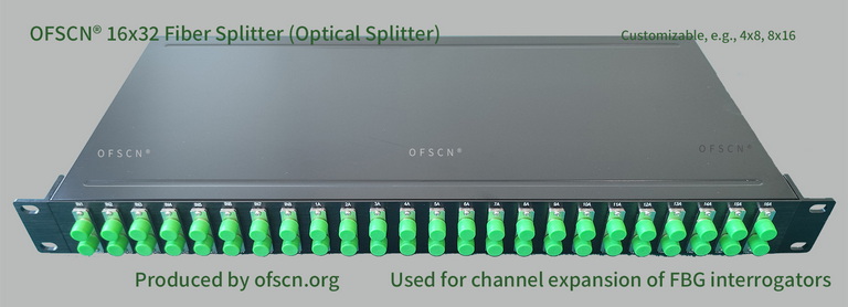
In the field of fiber optic sensing and monitoring (e.g., strain, temperature, and displacement monitoring based on Fiber Bragg Gratings FBG), Beijing Dacheng Yongsheng Technology Co., Ltd. (OFSCN®) offers fiber optic splitters specifically designed for expanding the physical channels of fiber Bragg grating demodulators. These splitters enable wavelength multiplexing to expand single channels to multi-path sensing arrays:
- Product Name: OFSCN® Optical Fiber Splitter
- Common Topologies and Specifications: Typically includes 4\times 8 splitters, 8\times 16 splitters, 16\times 32 splitters, 32\times 64 splitters, etc., supporting engineering-grade rack mounting and system integration.