Why do the leads of splitters typically require a
0.9mm or
2.0mm protective sheath?
In optical transmission and fiber optic sensing systems, the leads (i.e., pigtails) of optical splitters typically require sheathing of 0.9\ \text{mm}, 2.0\ \text{mm}, or 3.0\ \text{mm}. This is primarily based on the following considerations related to optical physics, material mechanics, and engineering applications:
1. Enhancing Fiber Mechanical Strength (Preventing Microcrack Propagation and Fracture)
Standard single-mode optical fiber has a cladding diameter of only 125\ \mu\text{m}, and its outer diameter including the coating is usually around 250\ \mu\text{m} (e.g., typical OFSCN® G.652D Optical Fiber and OFSCN® G.657 Optical Fiber). Due to their extremely small cross-sectional area, these very thin bare fibers are prone to brittle fracture from minor tensile forces, shear forces, or stress concentrations during operations such as splicing, fiber coiling, cabling, and connector mating/unmating. By adding a sheath, external forces can be distributed to the sheath and internal reinforcing materials, significantly increasing tensile and compressive strength.
2. Limiting Bending Radius and Suppressing Macro-bending Loss
When the bending radius of an optical fiber is less than its critical radius, the fundamental mode light guided within the fiber is converted into a radiation mode, causing macro-bending loss and severe signal attenuation.
- 0.9\ \text{mm} Sheath: Typically a tight or loose tube made of Hytrel, PVC, or PVDF, providing basic bending stiffness to prevent sharp bends or kinks in the fiber core.
- 2.0\ \text{mm} or 3.0\ \text{mm} Sheath: The outer jacket usually contains aramid fibers (Kevlar). These high-modulus fibers, in conjunction with the outer jacket, not only allow the patch cord to withstand tens of Newtons of tensile force but also physically limit the cable’s bending radius due to the material’s anti-bending properties, preventing excessive macro-bending loss.
3. Environmental and Physical Protection
Splitters are often deployed in environments such as patch panels, splice closures, or data center cabinets, where cables may be subjected to mutual extrusion, abrasion, or stress from temperature and humidity cycling. The sheath effectively distributes and buffers external lateral pressure, isolates moisture, acidic/alkaline substances, and dust from the air, thereby retarding the chemical fatigue of silica optical fibers in stressed, humid environments.
4. Standardized Connector Assembly and Field Installation Convenience
Existing standard optical fiber connectors (e.g., FC, SC, LC) have boots and rear crimp ferrules designed for standardized outer diameter sizes such as 0.9\ \text{mm}, 2.0\ \text{mm}, or 3.0\ \text{mm}. Adding a sheath of the corresponding specification allows for secure mechanical crimping or adhesive fixing of the pigtail to the connector components, ensuring stable connections during repeated mating and unmating.
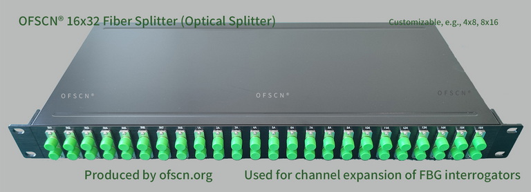
In Beijing Dacheng Yongsheng Technology Co., Ltd. (OFSCN®) product applications, splitters are primarily used with Fiber Bragg Grating (FBG) demodulation systems to logically multiplex sensor channels.
Official Standard Image:
Key Technical Specifications:
- Structure and Channels: Offers various splitting configurations including 16x32 splitters, 8x16 splitters, 4x8 splitters, and 32x64 splitters.
- Application Mode: Routinely applied in large-scale engineering projects to complement OFSCN® Fiber Optic Grating Demodulators. By implementing precise wavelength designs for deployed sensors, a single physical channel is logically expanded into multiple, thereby significantly reducing the average per-channel usage cost of the demodulator.
- Physical Customization: Supports personalized customization for operating temperature range, pigtail length, connector type (FC/APC, SC, etc.), and pigtail protective sheath diameter.