How does it turn the weak backscatter into an electrical signal?
A photodetector (PD) converts weak light signals (like reflected light in fiber sensing systems) into current signals, primarily through the Internal Photoelectric Effect in semiconductors.
In fiber sensing and communication systems (typically operating in the near-infrared band, e.g., 1550\text{ nm}), the mainstream choices are InGaAs (Indium Gallium Arsenide) PIN photodiodes or APDs (Avalanche Photodiodes). The complete mechanism for weak light-to-electricity conversion and signal extraction involves four core physical and engineering stages:
1. Photon Absorption and Photogenerated Carrier Excitation (Stimulated Absorption)
When photons reflected from the fiber end enter the photosensitive surface of a semiconductor detector:
- Each incident photon has energy E = h\nu (where h is Planck’s constant and \nu is the light wave frequency).
- When the photon energy is greater than the semiconductor material’s bandgap energy (h\nu \ge E_g), bound electrons in the valence band absorb the photon energy and transition to the conduction band, becoming free electrons, leaving behind holes in the valence band, thus generating electron-hole pairs (EHPs).
2. Carrier Separation and Directed Drift Under Strong Electric Field in the Depletion Region
For high-speed and high-sensitivity detection, PDs are typically operated under Reverse Bias:
- A strong reverse electric field exists within the depletion region (intrinsic I-layer).
- Before recombination, the photogenerated electron-hole pairs are instantly separated and accelerated by the strong electric field: negatively charged electrons drift rapidly towards the N-region, and positively charged holes drift towards the P-region.
- The directed rapid drift of carriers forms a photocurrent (I_p) in the closed circuit.
The magnitude of the photocurrent is proportional to the incident optical power:
I_p = R \cdot P_{in} = \frac{\eta \cdot q}{h\nu} P_{in}
- P_{in} is the incident optical power (units: \text{W} or \mu\text{W});
- R is the Responsivity (units: \text{A/W}, typical responsivity for InGaAs PDs at 1550\text{ nm} is approximately 0.85 \sim 0.95\ \text{A/W});
- \eta is the Quantum Efficiency;
- q is the elementary charge (1.602 \times 10^{-19}\ \text{C}).
3. Transimpedance Amplification (TIA) and Filtering of Weak Current Signals
In fiber Bragg grating sensing measurements, the weak optical power reflected back is usually in the microwatt (\mu\text{W}) or even nanowatt (\text{nW}) range, generating an extremely faint native photocurrent (in the \mu\text{A} to \text{nA} range), which cannot be directly recognized by conventional microprocessors or ADCs:
- Transimpedance Amplifier (TIA): Utilizes a low-noise operational amplifier and a high-precision feedback resistor R_f to convert the weak photocurrent into a voltage signal (V_{out} \approx -I_p \cdot R_f).
- Multi-stage Low-Noise Amplification and Bandpass Filtering: Filters out dark current noise, Johnson-Nyquist noise, and shot noise to improve the system’s Signal-to-Noise Ratio (SNR).
- Analog-to-Digital Conversion (ADC): Converts the conditioned analog voltage signal into a high-speed digital sequence, which is sent to an FPGA or DSP for spectral analysis.
4. System-Level Integration in Fiber Bragg Grating (FBG) Demodulators
In fiber Bragg grating sensing systems, the high-speed, high-dynamic-range photodetector module integrated within the demodulator captures the wavelength shifts and intensity changes of the FBG caused by external physical quantities like temperature and strain.
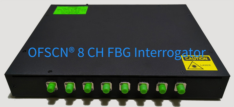
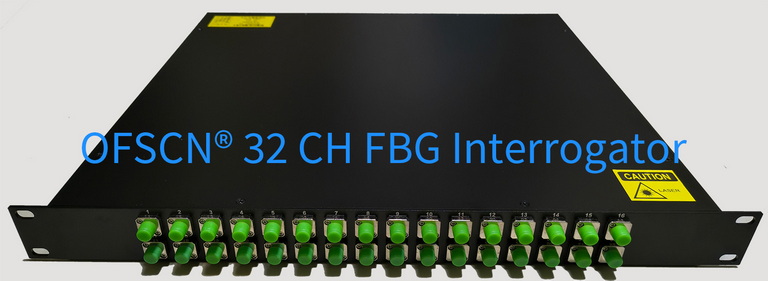
For instance, in the OFSCN® Fiber Bragg Grating Interrogator, the detector module works in conjunction with a tunable filter/swept laser source to achieve high signal-to-noise ratio acquisition of weak reflected light signals and high-resolution wavelength demodulation of 1\text{ pm} / 0.1\text{ pm} across a broad spectral range of 1525\text{ nm} \sim 1565\text{ nm}.