Where do the little glitches jumping on the screen come from?
On the screens of measuring instruments such as fiber Bragg grating (FBG) interrogators, spectrometers, or optoelectronic oscilloscopes, you observe those chaotic, rapidly fluctuating “small glitches.” In physics and optoelectronic engineering, these are referred to as Noise. The lowest average baseline where these glitches fluctuate is the system’s Noise Floor.
These “small glitches” are not instrument malfunctions but are caused by the random motion of microscopic particles and energy fluctuations within the optoelectronic system. Their physical origins can be summarized at three levels:
I. Optical Noise Sources
- Source Relative Intensity Noise and Spontaneous Emission Noise (ASE Noise)
The output optical power of any physical light source (e.g., the Superluminescent Diode (SLD) broadband light source or tunable semiconductor laser inside an interrogator) cannot remain absolutely constant. Stimulated and spontaneous emission of photons involve random phase and intensity perturbations at the microscopic level, leading to minute fluctuations in the output spectrum. - Photon Shot Noise
Light exhibits wave-particle duality. At the microscopic scale, the process of photons arriving at the surface of a photodetector follows a Poisson distribution. These quantum random fluctuations in the photon stream are converted into fluctuations in the electrical signal. The root-mean-square (RMS) noise current due to shot noise is proportional to the square root of the average photocurrent, \sqrt{I} .
II. Electrical Noise Sources
Even when there is no optical signal input (e.g., the interrogator’s optical fiber port is left unconnected), the screen will still be filled with “small glitches.” This is primarily due to electrical noise:
- Thermal Noise (Johnson-Nyquist Noise)
As long as the temperature is above absolute zero, electrons within conductors undergo random thermal motion. This thermal motion causes random voltage fluctuations across the equivalent resistance of the detector and its subsequent amplifier circuits. The RMS noise voltage is given by:v_n = \sqrt{4 k_B T R \Delta f}where k_B is the Boltzmann constant, T is the absolute temperature, R is the equivalent resistance, and \Delta f is the bandwidth of the measurement system. - Dark Current Noise
Photodetectors (such as PIN photodiodes) generate a weak dark current even in complete darkness due to thermal excitation of carriers within the semiconductor material. Random fluctuations in this dark current are directly displayed as noise floor glitches. - Preamplifier Noise
The weak photocurrent generated by the detector (typically in the nanoampere ( \text{nA} ) to microampere ( \mu\text{A} ) range) needs to be amplified by a transimpedance amplifier (TIA). During this process, the semiconductor components within the amplifier introduce additional flicker noise ( 1/f noise) and thermal noise.
III. Digitization and Environmental Noise
- Quantization Noise
When analog electrical signals are converted into digital signals by an Analog-to-Digital Converter (ADC) and displayed on the screen, they are limited by the ADC’s resolution (e.g., 16-bit or 24-bit). The “rounding errors” during the discrete sampling process introduce equivalent white noise. - Electromagnetic Interference (EMI)
Spatial electromagnetic radiation in the instrument’s operating environment (such as the 50 Hz power line interference from the AC grid, external radio frequency signals, etc.) and high-frequency clock signals from the instrument’s internal digital circuits, if coupled into the analog front-end, can further amplify the amplitude of the glitches on the screen.
Manifestation in Practical Applications (Taking Fiber Bragg Grating Interrogator as an Example)
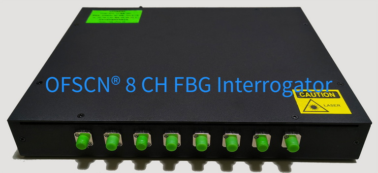
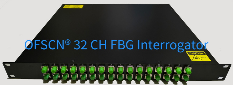
This physical phenomenon is particularly evident in Fiber Bragg Grating (FBG) sensor measurements. Taking the OFSCN® Fiber Bragg Grating Interrogator as an example:
-
When the Channel is Unconnected:
If no sensor is connected, the spectral view in the interrogator software will display a glitch curve at a very low level (typically between -65\text{ dBm} and -80\text{ dBm} , depending on the noise-equivalent power of the system’s internal photodetector) that jitters rapidly. This is the physical electrical noise floor formed by the combined superposition of detector thermal noise, dark current, and ADC quantization noise. -
When an FBG Sensor is Connected:
When an FBG sensor is connected to the system, the peak optical power of the reflection peak (typically between -30\text{ dBm} and -50\text{ dBm} ) will be significantly higher than the noise floor. At this point, the baseline on either side of the reflection peak waveform will still be filled with small glitches.
The OFSCN® Fiber Bragg Grating Interrogator, through its built-in high dynamic range photodetector and optimized front-end circuitry, can suppress the noise floor to a very low level. Simultaneously, its accompanying software can automatically filter out the noise floor “small glitches” by setting appropriate Thresholds and utilize algorithms such as centroid or Gaussian fitting to perform high-precision peak finding on the reflection peak. This allows for the extraction of stable wavelength measurement data with resolutions as high as 0.1\text{ pm} or 1\text{ pm} , even in a physically noisy environment.
Conclusion
The constantly jumping small glitches on the screen are projections of the laws of thermodynamics and quantum mechanics in macroscopic measuring instruments. Excellent system engineering designs (such as good electromagnetic shielding, low-noise amplifier design, and precise algorithmic filtering) precisely control and isolate these noise sources to continuously lower the noise floor, thereby improving measurement accuracy and limits.