Does the splitting ratio change with wavelength across the C-band from 1525-1565nm?
Across the entire C-band from 1525\text{ nm} \sim 1565\text{ nm}, the Splitting Ratio and Insertion Loss of fiber splitters do indeed vary with wavelength. In optical engineering, this wavelength-dependent physical characteristic is typically quantified by a metric known as Wavelength Dependent Loss (WDL).
1. Why Does the Splitting Ratio Change with Wavelength?
The splitting principle and manufacturing process of fiber splitters dictate their sensitivity to wavelength:
- Fused Biconical Taper (FBT) Splitter:
FBT splitters are made by fusing and stretching two or more optical fibers. Their splitting mechanism relies on evanescent field coupling between the cladding and core within the stretched region. The coupling coefficient is highly dependent on the wavelength of the input light. For traditional FBT devices, the splitting ratio can fluctuate significantly with wavelength drifts, necessitating special broadband or multi-window designs to maintain relative uniformity over a wide band. - Planar Lightwave Circuit (PLC) Splitter:
PLC splitters use waveguides fabricated on a quartz substrate using semiconductor processes for splitting. Compared to FBT, PLC splitters offer excellent broadband characteristics. However, even within the 1525\text{ nm} \sim 1565\text{ nm} band, minor changes in material refractive index and waveguide modes occur across the entire range, leading to slight wavelength-related fluctuations in the splitting ratio and loss between output ports.
2. What is Wavelength Dependent Loss (WDL)?
WDL is a key metric for measuring the flatness of loss within the operating bandwidth of an optical passive device. It is defined as the difference between the maximum and minimum insertion loss across all channels within a specified wavelength range:
\text{WDL} = \text{IL}_{\max}(\lambda) - \text{IL}_{\min}(\lambda)
For high-quality PLC splitters, the WDL within the C-band (1525\text{ nm} \sim 1565\text{ nm}) is typically controlled to be below 0.3\text{ dB} \sim 0.5\text{ dB}.
3. Design Considerations in Engineering Applications (Example: FBG Sensing System)
In large Fiber Bragg Grating (FBG) sensing projects, splitters are often used in conjunction with high-precision FBG interrogators.
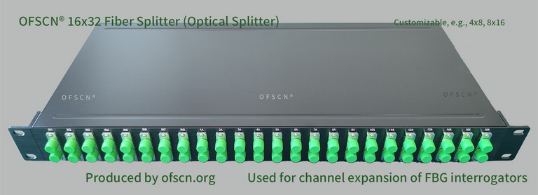
For instance, Beijing Dacheng Yongsheng Technology Co., Ltd.'s OFSCN® Optical Fiber Splitter is frequently employed as a channel expansion device for OFSCN® Fiber Bragg Grating Interrogator (with a default wavelength range of 1525\text{ nm} \sim 1565\text{ nm}). Using 1-to-many splitters (e.g., 16x32, 8x16), a single physical channel of the interrogator can be logically expanded into multiple, significantly reducing the system cost per channel.
Necessity of Strict Wavelength Design:
Due to the presence of WDL, the splitter exhibits different attenuations at different wavelengths within the C-band. This implies that:
- FBG sensors located at different wavelength positions (e.g., 1530\text{ nm} and 1560\text{ nm}) will experience different system losses when their reflected light returns to the interrogator.
- When performing an Optical Power Budget, the maximum insertion loss of the splitter (including maximum WDL) must be accounted for. This ensures that the intensity of all reflected FBG signals remains within the interrogator’s detection dynamic range, preventing signal loss due to wavelength-induced attenuation that could lead to the