Why can’t fiber optic cables be bundled too tightly with high-voltage power cables?
When bundling optical fibers (or fiber optic cables) too tightly with high-voltage power cables in fiber optic sensing and fiber optic communication engineering, it constitutes a serious violation of cabling standards. This practice introduces multiple adverse effects at the physical layer, leading to catastrophic impacts on optical signal transmission, the mechanical lifespan of the fiber, and the measurement accuracy of sensing systems.
The core physical mechanisms and engineering principles are primarily embodied in the following aspects:
1. Microbending & Macrobending Losses
When optical fibers are bundled too tightly with high-voltage power cables, the tie straps (or binding wires) exert significant lateral pressure on the surface of the cable locally.
- Microbending Losses: This localized compression causes micron-level geometric distortions in the fiber axis. This disrupts the total internal reflection (TIR) condition at the interface between the fiber core and cladding, coupling fundamental mode light that was propagating in the core into the cladding where it radiates away, resulting in noticeable signal attenuation.
- Macrobending Losses: High-voltage power cables (especially high-voltage, large-cross-section cables) typically have large bending radii and are extremely rigid. If optical fibers are forced into excessive bends while tightly pressed against them, the local bending radius of the fiber will be less than its permissible minimum bending radius, causing macrobending losses. This loss is particularly significant for networks using standard single-mode fibers (e.g., fibers compliant with the G.652D standard); even with bend-insensitive fibers (e.g., fibers compliant with the G.657 standard), excessive pressure can still exceed their bending tolerance.
2. Mechanical Stress & Micro-fractures in the Silica Matrix
The material of quartz optical fibers is silicon dioxide (\text{SiO}_2), which is essentially a brittle glass medium.
- Prolonged exposure to excessive localized lateral and tensile stresses can cause plastic deformation or even damage to the organic coating on the fiber surface.
- Without the protection of the coating, or under alternating stress, micro-fractures can form within the glass cladding of the fiber. Under environmental temperature variations and long-term static fatigue, these micro-fractures will gradually expand, ultimately leading to sudden physical fracture of the fiber and significantly shortening its engineering service life.
3. Thermal Expansion & Strain Coupling
High-voltage power cables generate substantial Joule heat during normal operation (especially under high load, overload, or short-circuit conditions), causing a significant temperature rise and volumetric expansion of the cable itself.
- The sheath materials of cables (such as Polyvinyl Chloride - PVC or Cross-linked Polyethylene - XLPE) have relatively large coefficients of thermal expansion, whereas the coefficient of thermal expansion for the quartz material of optical fibers is very small.
- If optical fibers are bundled too tightly with cables, the immense mechanical deformation caused by the cable’s thermal expansion or contraction will be directly translated into axial tensile force or radial compressive force acting on the fiber.
- Sensing Measurement Errors: In fiber optic sensing engineering (e.g., using Fiber Bragg Grating (FBG) temperature sensors for temperature measurement of high-voltage cable joints, or using Distributed Fiber Optic Sensing systems (DTS)/DOFS for full-line temperature measurement), this unintended external mechanical stress directly couples into the optical fiber. This leads to extremely severe temperature-strain cross-sensitivity issues for sensors based on wavelength shifts due to strain or temperature, resulting in significant measurement errors or high-frequency false alarms within the system.
4. Electromagnetic Force and Mechanical Vibration Coupling
When large currents flow through high-voltage cables (especially AC power at industrial frequencies), continuous mechanical vibrations at industrial frequencies (such as 50\text{ Hz} or 60\text{ Hz} electromagnetic vibrations) are generated due to electromagnetic induction within the cable body and between support structures.
- If the bundling is too tight, these physical vibrations are transmitted directly to the optical fiber without attenuation.
- For phase-sensitive distributed fiber optic sensing systems (such as Distributed Acoustic Sensors (DAS) based on coherent optical detection), these external mechanical vibrations and noise introduce severe background interference, reducing the sensing signal-to-noise ratio.
Recommended Cabling Standards and Practices
To prevent the aforementioned physical damage, fiber optic sensing engineering should adhere to the following practices during cabling:
- Use Non-Constricting Fixation: When laying fiber optic cables in the same channel as power cables, use dedicated cable clamps, cable hooks, or Velcro straps for binding. The binding force should be such that the cable can be gently slid but not detached; it is strictly forbidden to use nylon cable ties to tighten and constrict them.
- Maintain Safe Distance or Independent Conduits: Where space permits, low-voltage fiber optic cables should be laid in separate layers or compartments from high-voltage power cables to avoid direct contact.
- Select High-Pressure-Resistant Sheath and Armored Cables: If the site conditions are complex and direct bundling or installation in high-side-pressure environments is unavoidable, traditional soft PVC sheathed fiber optic patch cords should be abandoned in favor of metallic armored cables with high pressure and tensile resistance.
Recommended Industrial-Grade Armored Fiber Optic and Cable Solutions
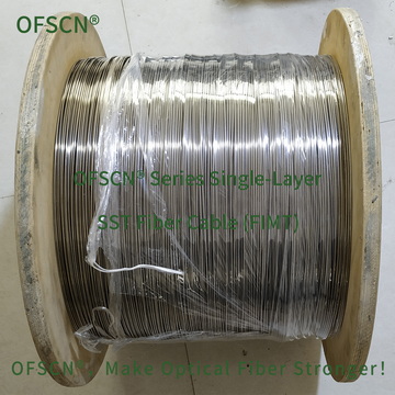
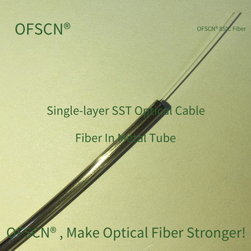
Within the Beijing Dacheng Yongsheng Technology Co., Ltd. (OFSCN®) technology portfolio, to address fiber optic sensing engineering challenges in high-side-pressure, high-tensile, and high-thermal-expansion environments such as cable temperature measurement, the following high-protection-grade seamless stainless steel tube armored or stranded steel wire structures are recommended:
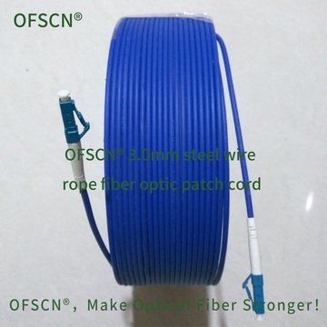
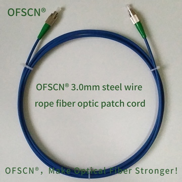
1. OFSCN® 3.0mm Steel Wire Rope Fiber Optic Patch Cord
This product integrates a seamless stainless steel tube with a stranded steel wire outer sheath, offering exceptionally superior physical protection. It can completely shield against external tension and side pressure, with a compressive strength greater than 200\text{ Mp} and a tensile strength greater than 1200\text{ N}. It is highly suitable for deployment in high-voltage cable trays or environments with high mechanical loads.

2. OFSCN® 85°C Seamless Steel Tube Fiber Cable
Utilizes a single layer of seamless stainless steel tubing for tight encapsulation, providing high wall hardness and excellent lateral support. Built with single-mode or multi-mode optical fibers, it completely isolates microbending stresses caused by overly tight cable ties, ensuring stable transmission of sensing optical signals. It is suitable for distributed fiber optic temperature sensing systems in power grids.