1x2 splitter output optical power is 50/50? Why pursue power equalization?
In optoelectronic engineering and fiber optic transmission systems, the optical power distribution of splitters (Splitter / Coupler) has rigorous physical definitions and application considerations. Here are detailed answers to your two questions:
1. Is the optical power output of a 1 \times 2 splitter 50/50?
Not necessarily. The coupling ratio of a 1 \times 2 optical splitter is entirely dependent on its physical structure design and manufacturing process.
- Balanced Splitter:
Its coupling ratio is 50/50. In this design, the single input optical signal is evenly divided into two, with the optical power of each output theoretically accounting for 50\% (approximately 3\ \text{dB} power loss per path, disregarding insertion loss and additional loss of the fiber optic component). - Unbalanced Splitter:
Its coupling ratio can be customized according to actual engineering needs, such as 10/90, 20/80, 5/95, or even 1/99, etc. This unbalanced design is commonly used for power monitoring (Tap port) in optical networks, bus topology structures, or to compensate for different optical losses in branches due to varying transmission distances.
2. Why pursue power averaging (equal splitting)?
In most standard optical communication and fiber optic sensing (e.g., Fiber Bragg Grating FBG sensing) system designs, balanced splitters are the most commonly used devices. The pursuit of power averaging is primarily based on the following three core engineering considerations:
(1) Optimizing the Dynamic Range and Signal-to-Noise Ratio (SNR) of Photodetectors
Photodetectors (PDs) or the optoelectronic conversion chips in demodulators have a specific optimal reception power range (i.e., linear dynamic range).
- Preventing Signal Overload and Saturation: If uneven splitting causes excessive optical power in one path, it may lead to saturation of the photodetector at the receiving end, resulting in signal distortion, clipping, or even damage to sensitive components.
- Ensuring SNR for Weak Signals: Simultaneously, the optical power in the path with less splitting might be too low. When the signal returns to the detector, it may be obscured by system thermal noise or shot noise, leading to a severe deterioration of the signal-to-noise ratio (SNR).
- Averaging power (50/50) ensures that the optical power budgets for subsequent measurement channels are highly consistent, making the decision thresholds for signal reception and processing algorithms more unified and simpler.
(2) Ensuring Maximum Contrast (Fringe Visibility) in Interferometric Systems
In optical sensing systems based on the principle of interference (such as Mach-Zehnder or Michelson interferometers), to achieve maximum interference fringe contrast (i.e., the largest difference between the maximum and minimum light intensity, theoretical visibility V \approx 1), the amplitudes (i.e., power) of the two beams participating in coherent interference must be exactly equal. Uneven splitting from the splitter will lead to a decrease in interference fringe contrast, severely reducing the accuracy of phase demodulation.
(3) Simplifying Link Loss Budget for Complex Multi-channel Systems
In large-scale fiber optic sensing projects, to achieve economical channel expansion, optical splitters are often used to expand the physical channels of Fiber Bragg Grating demodulators.
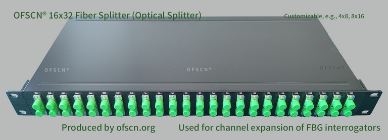
For instance, when using OFSCN® Optical Fiber Splitter (such as conventional 16 \times 32, 8 \times 16 splitters) with Fiber Bragg Grating demodulators, equally splitting splitters ensure that each logically expanded channel has the same optical attenuation baseline. This greatly simplifies the system integrator’s overall fiber link loss calculations. As long as the wavelength design is rigorous, it can ensure that the FBG reflection signals from each branch are displayed uniformly in the demodulation spectrum.