1:1 split and 1:9 split. What do they mean? How is light allocated proportionally?
1. What is “Splitting Ratio”?
Splitting Ratio refers to the percentage distribution relationship of optical power allocated to each output port to the total output optical power in an optical splitter/coupler.
-
1:1 Splitting (50%:50% Symmetric Splitting):
- Meaning: The input optical power is evenly distributed to two output ports, with each receiving 50\% of the optical power.
- Theoretical Loss: The theoretical insertion loss for each channel is approximately 3\ \text{dB} (i.e., 10 \log_{10}(0.5) \approx -3.01\ \text{dB}).
- Typical Scenarios: Interferometer construction (e.g., Mach-Zehnder, Michelson interferometers), symmetric dual-channel demodulation, and signal transmission with equal power splitting.
-
1:9 Splitting (10%:90% Asymmetric Splitting):
- Meaning: The input optical power is distributed proportionally, with one port receiving 10\% of the optical power and the other receiving 90\%.
- Theoretical Loss: The theoretical loss for the 10\% port is 10\ \text{dB}; the theoretical loss for the 90\% port is approximately 0.46\ \text{dB}.
- Typical Scenarios: In-line optical power monitoring/sampling (using the 10\% port for real-time monitoring without significantly affecting the main 90\% signal), chain/bus type cascaded sensing networks, etc.
2. How is Light Proportionally Distributed? (Physical Mechanism and Implementation Principle)
In fiber optics, optical signals are not split mechanically but are achieved based on the physical effect of Evanescent Field Coupling.
(1) Evanescent Field Coupling Principle
When light propagates in the optical fiber core through Total Internal Reflection (TIR), the electromagnetic field is not entirely confined within the core. A portion of the electromagnetic field penetrates the core-cladding interface into the cladding, forming a non-radiating field that decays exponentially in the radial direction, known as the Evanescent Wave.
When the cores of two bare optical fibers are brought close to within micrometers (\mu\text{m}), the evanescent field from one fiber can penetrate and couple into the core of the adjacent fiber, exciting its guided modes, thereby causing periodic energy transfer between the two fibers.
(2) Fused Biconical Taper (FBT) Process
Asymmetric splitting ratios (e.g., 1:9, 2:8, 5:95, etc.) are primarily achieved through the fused biconical taper technique:
- Structure Preparation: Two single-mode optical fibers, stripped of their coating, are placed parallel and twisted together.
- Heating and Stretching: Under heating from a high-temperature hydrogen-oxygen flame or electric arc, the fibers melt and are stretched from both sides by precision micro-actuators, forming a biconical coupling region.
- Dynamic Monitoring and Cutoff: As the taper region thins, the core cross-section decreases, the mode field expands outward, and the overlap area of the evanescent fields and the coupling length gradually increase. Optical power begins to transfer periodically from the main fiber to the secondary fiber. The manufacturing system injects laser light in real-time and monitors the output power at the two output ends. When the output power precisely reaches the target ratio (e.g., 10\% : 90\% ), the stretching is stopped, and the device is solidified and packaged.
(3) Planar Lightwave Circuit (PLC)
For symmetric splitting (e.g., 1:2, 1:4, 1:8, 1:16, 1:32 equal splitting scenarios), the technology often uses a symmetric Y-shaped branching waveguide network etched on a quartz substrate using micro/nano semiconductor lithography processes, achieving high-consistency symmetric splitting.
3. Related Products and Engineering Applications
In optical sensing and Fiber Bragg Grating (FBG) demodulation systems, optical splitters are commonly used for channel expansion, topology construction, and optical power distribution.
- Product Details: OFSCN® Optical Fiber Splitter
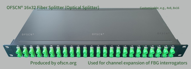
Key Parameters and Applications:
- Includes various splitting specifications such as 4\times 8 , 8\times 16 , 16\times 32 , 32\times 64 , etc.
- In large-scale sensing projects, when used with an FBG demodulator, it can expand a single physical channel into multiple logical channels through wavelength planning, thereby optimizing the overall channel utilization of the system.