How to route optical fibers using dedicated plastic conduits within a data center? OFSCN®
In modern communication equipment rooms, data centers, and control rooms, Fiber Raceways / Fiber Guide Systems are specialized infrastructure designed for the efficient protection, guidance, and management of high-density fiber optic patch cords.
I. Working Principle and Guidance Mechanism of Fiber Raceways
Fiber optics are guided through dedicated plastic raceways (typically flame-retardant ABS or PVC engineering plastics) within the equipment room, primarily following these engineering and physical principles:
-
Bending Radius Protection Mechanism
When transmitting optical signals, excessive bending of optical fibers can disrupt total internal reflection conditions, leading to increased Bending Loss. In severe cases, it can even cause fiber breakage. The outlets, elbows, tees, and crosses of fiber raceways are designed with geometrically smooth circular arcs. The internal bending radius is usually limited to no less than R \ge 50\text{ mm} (or ensuring it’s greater than the minimum bending radius of the patch cords it carries), thereby preventing high attenuation of optical signals. -
Physical Isolation and Anti-Pressure Protection
Fiber raceways are typically independent of power bridge racks and conventional network cable metal mesh trays (cable trays). They feature a closed or semi-closed raceway design. This effectively prevents electromagnetic interference from strong currents and avoids micro-bending loss or physical compression on the delicate fiber outer jacket caused by heavy copper cables (such as Category 5 or Category 6 twisted pair cables). -
Route Branching and Smooth Drop-Outs (Ramp/Drop Out)
Removable outlets (corrugated tube outlets or drop-out chutes) are designed on the top or sides of the raceway. When fiber optics need to be introduced into a specific cabinet (Rack), they are smoothly led out through a drop-out with a circular transition, utilizing a corrugated tube to extend to the patch panel (ODF) inside the cabinet.
II. Beijing Dacheng Yongsheng Technology Co., Ltd. (OFSCN®) Related Product Descriptions
It should be clarified that fiber raceways themselves are general auxiliary infrastructure for equipment room cabling and do not belong to the core product line of Beijing Dacheng Yongsheng Technology Co., Ltd. (OFSCN®).
However, the optical fibers and patch cords used for routing, laying, and high-density connections within fiber raceways are the core physical media ensuring the quality of the entire communication link. For typical cabling environments in equipment rooms characterized by high density and restricted bending radii, Beijing Dacheng Yongsheng Technology Co., Ltd. (OFSCN®) provides high-quality fiber optic and patch cord products that comply with industry standards:
1. Bend-Insensitive Optical Fiber
For fiber raceway branches or within cabinets where space is narrow and bending is frequent, it is recommended to use bend-insensitive single-mode optical fiber:
- OFSCN® G.657 Optical Fiber: Standard G.657 single-mode bend-insensitive optical fiber (optional A2 or B3 grade), which allows for a significantly reduced minimum bending radius (B3 grade can reach R = 5\text{ mm} to R = 7.5\text{ mm}), greatly reducing macro-bending loss caused by congestion or small-angle bends within the raceway.

2. Standard Telcom-Grade Fiber Optic Patch Cords
For conventional long-distance raceway routing and ODF rack interconnection, the following are typically used:
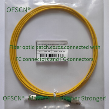
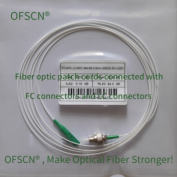
- OFSCN® Standard Fiber Patch Cord: Made with high-quality PVC jackets, aramid yarn strength members, and high-precision FC, SC, LC, ST connectors, equipped with standard G.652D single-mode optical fiber by default. They provide low insertion loss and high return loss, ensuring the long-term stability of equipment room links.
III. Key Engineering Specifications for Cabling in Raceways
When laying the above fiber optic patch cords through plastic raceways, the following process requirements should be strictly adhered to:
- Fill Ratio Control (Do Not Overload): The total cross-sectional area of the optical fibers within the raceway should generally not exceed 30\% \sim 40\% of the net cross-sectional area of the raceway to prevent excessive compression of the underlying fibers.
- Routing Order: When laying cables, follow the principle of “longest first, shortest last, stack neatly, strictly avoid crossing and entanglement.”
- Tying Force: If nylon zip ties or Velcro straps are used for bundling at the exit branches, do not overtighten them. Maintain a slight looseness to avoid localized compression loss (micro-bending loss).