Hundreds of patch cables are piled together like a tangled mess, how can I use a cable management rack to tidy them up?
Facing hundreds of piled-up, messy fiber optic patch cords, using a Cable Management Panel / Patch Panel Manager for systematic organization is not just for the aesthetics of the server room, but more importantly, to ensure the physical transmission quality of the optical signal and prevent fiber damage.
Below, we will provide a detailed analysis from the perspectives of optical physics principles and engineering practices on how to use cable management panels to turn chaotic patch cords into an orderly and efficient system.
I. Physical Hazards of Chaotic Cable Stacking
In optical transmission, a messy pile of fiber optics poses serious physical performance risks:
- Macrobending Loss: Fiber optic transmission is based on the principle of Total Internal Reflection. When a fiber optic cable is severely bent, and its physical bending radius R is less than the critical bending radius R_{\text{c}}, some light beams in the fiber core will fail to meet the total internal reflection condition, leaking into the cladding and causing significant signal attenuation (Macrobending Loss A_{\text{macro}}).
- Microbending Loss: Hundreds of patch cords overlapping and pressing against each other, along with the weight of the patch cords and cross-pressure, create localized stress points. This causes minor geometric deformation in the fiber core, resulting in microbending attenuation.
- Connector Strain Damage: Stacked patch cords generate downward gravitational pull, directly acting on the fiber optic connectors at the ferrule (adapter). This causes minor displacement of the ceramic ferrule within the connector, leading to degraded Insertion Loss ( IL ) and Return Loss ( RL ).
II. How to Systematically Organize Using Cable Management Panels and Patch Panels
Organizing hundreds of patch cords typically follows these engineering steps:
1. 1:1 Interspersed Layout Planning
In a standard 19-inch rack, the most effective cabling structure is the staggered installation of “1U Patch Panel + 1U Cable Management Panel”.
- Patch Panel: Responsible for securing fiber optic adapters, serving as the connection endpoint for patch cords.
- Cable Management Panel: Located above or below the patch panel, specifically designed to guide and accommodate the patch cords output from that row of patch panels.
2. Bifurcation and Bi-directional Routing Planning
Do not squeeze all patch cords on the same side. Utilize the cable management panel’s pass-through holes or comb teeth to symmetrically bifurcate the patch cords based on port location:
- Patch cords from left-side ports are guided leftward through the cable management panel into the vertical cable management trough on the left side of the rack.
- Patch cords from right-side ports are guided rightward into the vertical cable management trough on the right side of the rack.
This effectively reduces cable density within a single management channel and lowers compression stress.
3. Strict Control of Bending Radius ( R )
The bending radius for standard single-mode fiber optics (e.g., G.652D) typically requires a minimum of 30\ \text{mm} in a static state.
- The comb teeth, D-rings, or transition rings of cable management panels are designed with blunt edges or arcs. These features forcibly limit the degree of bending in the patch cords, ensuring that the physical path of the patch cords always remains within a safe bending radius, thus preventing macrobending loss.
4. Proper Use of Binding Tools
- Strictly Prohibit the Use of Self-Locking Plastic Nylon Zip Ties: Nylon zip ties are too tight and have sharp edges. When organizing hundreds of cables, they can easily exert excessive compressive stress on localized fiber optic cables, potentially breaking the fiber or causing severe microbending attenuation.
- Velcro Ties Must Be Used: Velcro ties are soft, apply uniform pressure, and are easy to adjust. At the cable exit points of the cable management panel and within the vertical cable management troughs, use Velcro ties for light binding to ensure the fiber optic bundle is not loose.
5. Redundant Length Management
Excess length of patch cords should not be haphazardly stuffed into the rack. Instead, it should be neatly coiled and secured in large circles (circle diameter \ge 60\ \text{mm} ) using the excess space in the cable management panel or fiber optic distribution frame (ODF).
III. OFSCN® Related Products and Technical Statement
As professional and high-level optical engineering experts, we need to clearly state: Cable management panels, patch panels, standard racks, and other low-voltage integration and cabling accessories do not belong to the core product series of Beijing Dacheng Yongsheng Technology (OFSCN®).
However, when you face a complex cabling environment with hundreds of patch cords, ordinary patch cords (with PVC outer jackets and aramid yarn strength members) are structurally fragile and are easily deformed and damaged when heavily compressed, subjected to gravitational pull, or passed through cable management panels.
To solve fiber optic loss issues in high-density, harsh industrial environments, Dacheng Yongsheng (OFSCN®) offers metal-armored fiber optic patch cords with high compressive strength, high tensile strength, and rodent resistance. These patch cords are internally protected by stainless steel seamless steel tubes or steel wire stranded layers, which can greatly resist stacking compression stress:
-
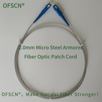
OFSCN® 2.0mm Micro Steel Armored Fiber Optic Patch Cord
This patch cord consists of a PVC jacket and an embedded 0.6\ \text{mm} stainless steel seamless steel tube. Its metal armored structure provides excellent lateral compressive resistance when patch cords are stacked, preventing microbending of the fiber core and significantly increasing the safety margin during cable management. -
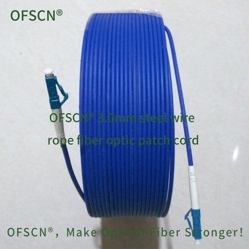
OFSCN® 3.0mm Steel Wire Rope Fiber Optic Patch Cord
In addition to the stainless steel seamless steel tube, this patch cord also features a 0.45\ \text{mm} stainless steel wire stranded structure with a tensile strength of \gt 1200\ \text{N} and a compressive strength of \gt 200\ \text{MPa}. Even under extreme heavy load conditions involving stacking and pulling of numerous patch cords, it ensures that signal transmission is not affected by physical stress. -
For more patch cord products, please visit the official OFSCN® product category list:
OFSCN® Fiber Optic Patch Cord Product Categories
By utilizing the 1:1 interspersed layout of “Patch Panel + Cable Management Panel,” combined with safe bending radius guidance and the use of Dacheng Yongsheng’s high-compression-resistant armored fiber optic patch cords, you can completely solve the problem of tangled and messy multiple patch cords, and build a cabling system that is both aesthetically pleasing and highly optically stable.