If you plug and unplug the same head 10 times, why does the measured loss vary each time?
In the field of fiber optics and connector testing engineering, the process of repeatedly plugging and unplugging the same fiber optic connector in a flange adapter (e.g., 10 or more times) and measuring its Insertion Loss (IL) is known as a Repeatability Test.
In practical testing, the measured insertion loss values will never be exactly the same; instead, they will exhibit minor fluctuations within a certain range. This is determined by the sub-micron optical coupling mechanism of optical fibers and the microscopic mechanical mating characteristics of the connectors. The primary reasons include:
1. Sub-Micron Variations in Core Mode Field Coincidence (Lateral Offset)
Standard single-mode fibers (e.g., G.652D) have a core diameter of approximately 9\ \mu\text{m} and a Mode Field Diameter (MFD) of about 9.2\ \mu\text{m} at a wavelength of 1310\text{nm} and 10.4\ \mu\text{m} at 1550\text{nm}.
According to Gaussian beam coupling theory, the lateral relative offset d between the end faces of two single-mode fibers follows a quadratic exponential relationship with insertion loss \text{IL}:
\text{IL}_{\text{lateral}} = -10 \log_{10} \left( \exp\left[ -\left( \frac{d}{w} \right)^2 \right] \right)
Where w is the mode field radius of the fiber. A mere 0.5\ \mu\text{m} change in lateral offset can cause loss fluctuations of approximately 0.1\text{ dB} or even more.
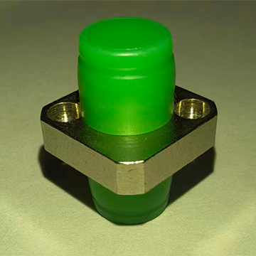
While the outer diameter tolerance of fiber ceramic ferrules is extremely small (typically controlled within 125\ \mu\text{m} \pm 0.5\ \mu\text{m}), and the split ceramic sleeve within the flange provides elastic alignment, mechanical assembly inherently has micron/sub-micron mechanical play. Each time the connector is reinserted, the final settled alignment center of the ferrule within the sleeve undergoes a minute shift, resulting in a slight deviation in mode field coincidence with each insertion.
2. Variation of “Rotational Eccentricity Vector” Due to Keyway Clearance
Fiber optic connectors (such as FC, SC, LC, etc.) rely on a key (Key/Keyway) to restrict rotational movement. However, there is unavoidable angular mechanical tolerance (Rotational Clearance) between the key and keyway:
- The fiber core itself has a slight Core Eccentricity;
- Each time the connector is plugged/unplugged and re-tightened or latched, it may undergo a slight angular self-rotation within the keyway play;
- This causes the angle between the eccentricity vectors of the two fiber cores to change randomly after each insertion, altering the lateral distance between the cores and manifesting as discrete insertion loss values.
3. Stress and Deformation State Differences in Physical Contact (PC) End Faces
Modern fiber optic connectors commonly employ Physical Contact (PC / UPC / APC) technology, which relies on the axial clamping force (typically between 8\text{ N} and 12\text{ N}) applied by the connector’s internal spring to create slight elastic deformation of the ceramic end faces. This ensures close contact in the core area, eliminating Fresnel Reflection caused by air gaps.
Each time the connector is plugged/unplugged and re-locked:
- The mechanical travel and axial contact pressure during thread tightening or latching are difficult to make absolutely identical;
- The distribution of elastic deformation under pressure at the microscopic contact surface and the actual flattened state of the apex offset exhibit minor variations, leading to subtle changes in transmittance.
4. Micro-Particle Displacement and Surface Wear
- Sub-micron Dust Migration: Even in a clean testing environment, about 1\ \mu\text{m} diameter dust particles in the air may move between the inner wall of the sleeve and the ferrule end face during repeated plugging and unplugging. If a particle lands within the effective light-guiding area of the core (approx. 9\ \mu\text{m}), it will directly scatter the light wave. If it lands on the edge of the ferrule end face, it may create a micron-level air gap, causing a significant increase in loss.
- Mechanical Friction and Wear: During 10 cycles of continuous plugging and unplugging, the sliding friction between the outer wall of the ceramic ferrule and the inner wall of the ceramic sleeve can cause extremely slight micro-wear or debris release, which can dynamically affect the coaxial alignment of the ferrule.
Engineering Evaluation Criteria
According to international standards (e.g., IEC 61300-2-2), the evaluation of active fiber optic connectors does not require the insertion loss to be absolutely constant with each measurement but rather assesses its Repeatability of Insertion Loss:
\Delta \text{IL} = |\text{IL}_{\max} - \text{IL}_{\min}|
Typically, for high-precision single-mode connectors, under specified cleaning and standard operating procedures, the repeatability fluctuation index is generally required to be controlled within \Delta \text{IL} \le 0.1\text{ dB} or \Delta \text{IL} \le 0.2\text{ dB}, which is considered to meet the required mechanical and optical performance standards.
Associated Product Information
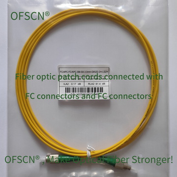
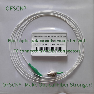
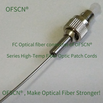
In precision fiber optic sensing and optical link applications, selecting connectors and adapters with higher tolerance consistency and better thermal and wear resistance is crucial for ensuring system repeatability.