What impact does a connector that is too tight or too loose have on the signal?
In the connection of fiber optic communications and fiber optic sensors (such as Fiber Bragg Grating FBG systems), fiber optic connectors (e.g., FC/PC, FC/APC, etc.) are precisely positioned by ceramic ferrules within an adapter (flange) and rely on an internal spring to provide moderate end-face contact pressure (Physical Contact, PC).
Connecting a fiber connector “too loosely” or “too tightly” essentially alters the physical contact state and stress environment of the fiber end faces, leading to the following specific physical and optical impacts on optical communication and sensing signals:
I. Connector Inserted Too Loosely (Insufficient Preload or Not Latched)
When a connector is not fully seated or the latch is loose, the fiber cores of the two ends cannot achieve good physical contact:
- Significantly Increased Insertion Loss (IL)
- Air Gap and Fresnel Reflection: A micro-gap forms between the end faces. Due to the refractive index mismatch between the fiber core (n_1 \approx 1.468) and air (n_2 \approx 1.0), Fresnel reflection occurs at the interface, causing a substantial attenuation of transmitted optical power.
- Axial/Angular Misalignment: Insufficient mechanical constraint leads to lateral displacement or angular tilt of the two fiber cores, preventing precise alignment of the optical spots and further reducing transmitted optical power.
- Degraded Return Loss (RL) (Dramatic Increase in Reflected Light)
- Uncontacted PC-flat end faces can have a reflectivity as high as 4\% (Return Loss as low as approximately 14\text{ dB}). Intense back-reflected light returns to the demodulator or light source, disturbing the stability of the light source emission and introducing interference noise in Fiber Bragg Grating (FBG) demodulation systems, causing wavelength identification drift or misjudgment.
- Signal Instability and Phase Noise
- Environmental micro-vibrations or airflow cause dynamic changes in the air gap distance, resulting in random power fluctuations (optical scintillation) and dynamic phase noise.
II. Connector Inserted Too Tightly (Excessive Pressure or Exceeding Rated Insertion Force)
Fiber connector ferrules typically have a slight spherical lapping. When the insertion and clamping force exceeds the design range:
- Permanent Physical Damage to the Fiber End Face
- Scratches and Chipping: Excessive stress can cause micro-cracks, pits, or chipping on the silica glass fiber core end face. Even if reconnected with standard force, the abraded end face will exhibit irreversible high insertion loss and low return loss due to increased scattering.
- Photoelastic Effect and Stress Birefringence (Impact on Wavelength/Polarization Sensitive Signals)
- Extremely high axial compressive stress on the fiber core causes microscopic deformation and uneven internal stress distribution in the glass material (photoelastic effect). This stress introduces Polarization Dependent Loss (PDL) and stress-induced birefringence, which can lead to reflection peak splitting or nonlinear wavelength shifts in polarization-maintaining fiber systems or high-precision FBG spectral measurements.
- Cracking or Plastic Deformation of the Adapter (Flange) Ceramic Ferrule
- Forceful over-insertion may cause permanent angular deformation or even fracture of the zirconia split sleeve inside the flange, leading to complete failure of subsequent mating precision.
III. Standard Connection and Recommended Devices
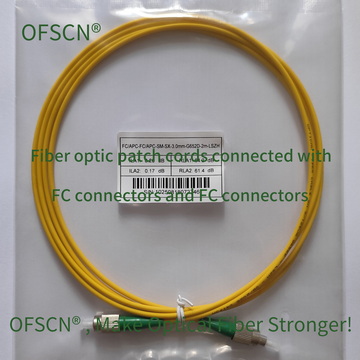
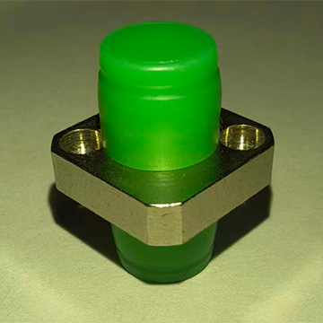
To ensure optimal physical performance for optical transmission, standard fiber interfaces (such as OFSCN® Standard Fiber Patch Cord) are designed with standard threaded locking mechanisms (FC type) or push-pull latches (SC/LC type). When used with standard OFSCN® High Temperature Resistant Fiber Optic Adapter, they provide a constant end-face preload (typically 7\text{N} \sim 12\text{N}), achieving stable low loss (typically \text{IL} \le 0.2\text{ dB}) and high return loss (APC end face \text{RL} \ge 60\text{ dB}).
In summary, appropriate insertion force and precise alignment are the physical foundations for ensuring low insertion loss, high return loss, and long-term system stability of fiber optic signals.