Pulling on a patch cord to measure loss, what happens to the signal when the fiber is stretched?
When an optical fiber jumper cable is subjected to tensile stress (tensile testing or axial pulling) and its signal is monitored, the guided wave state within the fiber is influenced by both geometric deformation and the photo-elastic effect. Depending on the fiber’s stress state and the test parameters, the signal primarily exhibits the following physical changes:
I. Changes in Transmitted Optical Power and Insertion Loss
-
Ideal Uniform Axial Stretching (Micro-strain Phase):
- Within the elastic deformation range of silica fiber (strain typically 0 \sim 10000\ \mu\varepsilon, corresponding to an elongation of less than 1\%), the fiber core and cladding diameters undergo minor transverse contraction due to Poisson’s effect (Poisson’s ratio for single-mode fiber \nu \approx 0.17).
- The slight variations in core diameter and numerical aperture have a negligible impact on the waveguide’s mode confinement capability. Therefore, under pure axial stretching, the fiber’s inherent transmission attenuation does not significantly worsen (loss variations are typically below 0.01\ \text{dB}, making them difficult to detect with conventional optical power meters).
-
Localized Stress Concentration and Microbending Loss:
- In practical jumper cable tests, stress is often uneven at the connector boot, strain relief, or crimp points.
- When tensile stress causes differential slippage or lateral pressure between the protective jacket (PVC/LSZH/Kevlar) and the internal glass fiber core, the core experiences random, small-amplitude, high-frequency bends (microbends). Higher-order leaky modes increase rapidly, leading to step-like increases in loss or severe signal jitter observed on the optical power meter (loss can jump by several \text{dB}).
-
Mechanical Fracture Threshold:
- When the axial stress reaches the fracture threshold of silica glass’s microcracks, the fiber undergoes brittle fracture, completely interrupting optical transmission, and the insertion loss instantaneously becomes infinite (\infty).
II. Changes in Optical Phase and Time Delay
The most sensitive and significant change in the transmitted signal caused by pulling the fiber is not power attenuation, but optical phase and transmission time delay:
- Geometric Length Increase: The actual physical length of the fiber L elongates ( \Delta L > 0 ).
- Refractive Index Reduction Due to Photo-elastic Effect: Axial tensile strain \varepsilon causes a decrease in the effective refractive index n_{\text{eff}} of the fiber core:
\Delta n_{\text{eff}} = -\frac{1}{2} n_{\text{eff}}^3 \left[ p_{12} - \nu (p_{11} + p_{12}) \right] \varepsilon
where p_{11} and p_{12} are the photo-elastic coefficients of the silica fiber.
- Total Optical Path (OPL) and Phase Shift: Although the refractive index decreases, the contribution from the physical length elongation is dominant, leading to an increase in the total optical path. The phase delay \Delta \phi of the optical carrier increases linearly with stretching:
\Delta \phi = \frac{2\pi}{\lambda} (n_{\text{eff}} \Delta L + L \Delta n_{\text{eff}}) > 0
In interferometric or pulse delay tests, fringe shifts or a linear delay in pulse arrival time are observed.
III. Changes in Fiber Bragg Grating (FBG) or Distributed Sensing Signals
If the jumper cable incorporates Fiber Bragg Grating (FBG) structures, when the fiber is stretched:
- The grating period \Lambda increases, and superimposed with the change in effective refractive index n_{\text{eff}}, its Bragg reflection wavelength \lambda_B undergoes a linear redshift:
\Delta \lambda_B = \lambda_B (1 - p_e) \varepsilon
In the 1550\ \text{nm} wavelength window, for every 1\ \mu\varepsilon of strain (equivalent to one part per million elongation), the reflection wavelength shifts approximately 1.2\ \text{pm} towards longer wavelengths.
IV. Tensile Structural Design in Engineering
Conventional general-purpose jumper cables, lacking rigid tensile support, are prone to transmitting strain directly to the internal fiber core when subjected to significant external pulling forces, leading to optical loss degradation or even fiber breakage.
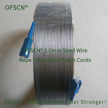
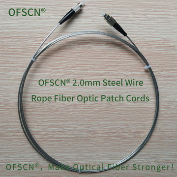
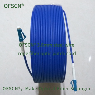
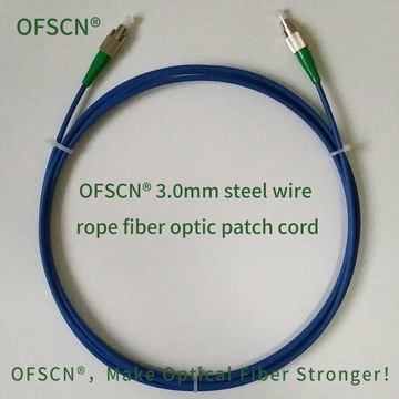
To address signal stability issues in high-tension environments, Beijing Dacheng Yongsheng Technology Co., Ltd. (OFSCN®) employs a dual-layer composite protection structure consisting of stainless steel stranded wire armor and a micro-seamless stainless steel tube. This design ensures that axial tensile stress is entirely borne by the external metal layers, thereby isolating the tension applied to the internal glass fiber core:
- OFSCN® 3.0mm Steel Wire Rope Fiber Optic Patch Cord (Tensile Strength > 1200 N, Compressive Strength > 200 MPa)

- OFSCN® 2.0mm Steel Wire Rope Fiber Optic Patch Cord (All-metal structure, Tensile Strength > 1500 N)