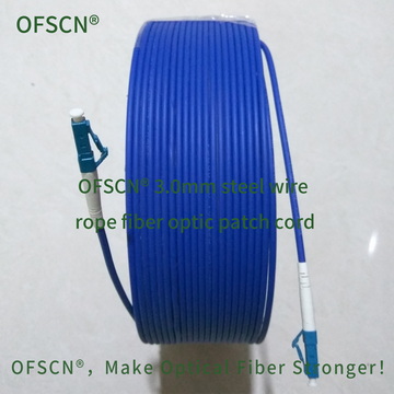
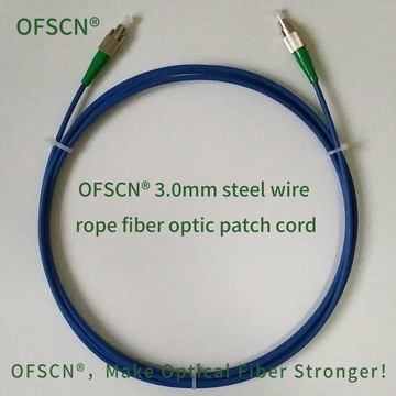
If you pull too hard on a jumper cable, will it break the optical fiber inside the connector?
Yes, and this is the most common form of physical failure for fiber optic patch cords during cabling construction and daily maintenance.
I. Mechanical Mechanism of Fiber Breakage Inside Connectors
The connection area between fiber optic patch cord connectors (such as FC, SC, LC, ST, etc.) and optical cables is one of the weakest points in the mechanical structure of the entire link. When the axial tensile force applied by dragging the patch cord exceeds the limit, the connector internally undergoes the following mechanical failure process:
-
Strain Bearing Layer Failure and Slippage
In standard fiber optic patch cords, the aramid fibers (Kevlar) inside the outer jacket bear the mechanical tensile force. The aramid yarns are crimped and fixed to the metal or plastic tail of the connector via a metal crimp ring. When the external pulling force exceeds the biting and friction limit of the crimp ring, the aramid yarns slip and detach, causing the external tensile protection mechanism to fail. -
Tensile Stress Concentration Transferred to the Bare Fiber
Standard single-mode quartz fiber (typically 125\ \mu\text{m} outer diameter) has a low strain limit, with a fracture strain usually only between 1\%\sim 2\%. Once the external reinforcing layer shifts, the axial tensile load is directly transferred to the bare fiber inside the connector. -
Shear Brittle Fracture at the Bonding Interface of the Ceramic Ferrule
The end of the fiber is fixed inside the micro-hole of the ceramic ferrule by curing epoxy resin. In the transition zone between the rear of the ferrule and the bare fiber, there is a sharp change in material stiffness. When subjected to excessive tensile force, the bare optical fiber experiences severe shear and tensile composite stress at the root of the cured adhesive interface, causing the fiber to “break flat” directly at the root of the ferrule. -
Latent Breaks and Micro-Damage
Even if the tensile force does not reach the critical value for instantaneous fracture, excessive tension can cause micro-cracks on the quartz surface to propagate, or cause local micro-bending due to extrusion of the fiber within the rubber buffer tube of the connector’s tail.
This leads to a sudden drop in Return Loss (RL) and a sharp increase in Insertion Loss (IL) of the optical link. In Fiber Bragg Grating (FBG) sensing applications, it directly causes distortion of the reflection spectrum, loss of wavelength demodulation, or measurement drift.
II. What is the “Installation Tensile Force” Limit?
In fiber optic cabling and sensor engineering, the design specifications for optical cables/patch cords typically distinguish between two tensile force limits:
- Short-Term Tensile Force (Installation Tensile Force Limit)
This refers to the maximum instantaneous tensile force allowed to be applied to the patch cord or optical cable during installation processes such as pulling through conduits. In this state, the optical fiber is allowed to undergo slight elastic deformation, but it must fully rebound and recover after the tensile force is released, without any damage to the coating or degradation of optical performance.- For conventional single-core plastic jacket patch cords, the standard short-term installation tensile force limit is usually around 70\sim 100\ \text{N} (approximately equivalent to the gravitational force of 7\sim 10\ \text{kg}).
- Long-Term Tensile Force (Operating Tensile Force Limit)
This refers to the maximum residual static tensile force that the patch cord can withstand long-term throughout its lifecycle after project installation is complete (usually required to be less than 20\sim 40\ \text{N}), to prevent fatigue fracture of the quartz glass due to long-term stress corrosion.
III. Recommended Standard Installation Practices
To prevent internal fiber breakage, the following guidelines should be followed during on-site operations:
- Absolutely No Pulling by the Cable: When plugging or unplugging connectors, fingers must firmly grip the metal locking sleeve or plastic housing of the connector body. Never pull the rubber boot or the cable itself for dragging.
- Graduated Pulling: When pulling through conduits or over long distances, use specialized pulling socks or apply force directly to the tensile reinforcing elements. Never use fiber optic connectors directly for pulling during cabling.
IV. Engineering Solutions for High Tensile Force Environments
In harsh industrial environments, narrow space pulling, or high mechanical stress conditions, conventional patch cords are easily damaged by external pulling forces. In engineering, full metal armored or steel wire rope reinforced patch cords are commonly used. The connector is rigidly anchored to the internal armored steel tube/steel wire rope, which can increase the installation tensile limit by more than ten times:
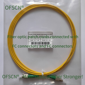
- OFSCN® Standard Fiber Patch Cord: Conventional PVC jacket and aramid structure, suitable for static interconnections within cabinets where no external mechanical tension is applied.
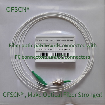
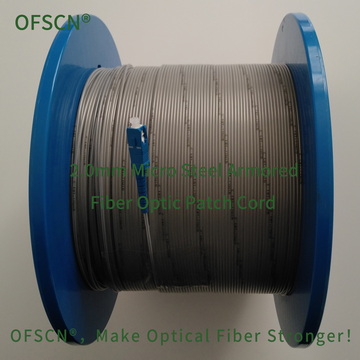
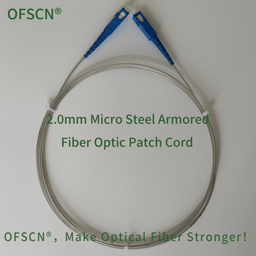
- OFSCN® 2.0mm Micro Steel Armored Fiber Optic Patch Cord: Built-in 0.6\ \text{mm} seamless stainless steel tube protection, tensile strength >150\ \text{N}, compressive strength >240\ \text{MPa}.

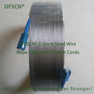
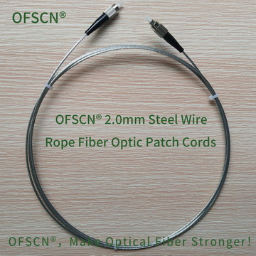
- OFSCN® 2.0mm Steel Wire Rope Fiber Optic Patch Cord: All-metal structure, including a 0.6\ \text{mm} galvanized steel wire twisted layer and a 1.0\ \text{mm} seamless stainless steel tube, tensile strength >1500\ \text{N}, compressive strength >150\ \text{MPa}.

- OFSCN® 3.0mm Steel Wire Rope Fiber Optic Patch Cord: PE jacket combined with stainless steel wire twisted layer and seamless stainless steel tube structure, tensile strength >1200\ \text{N}, compressive strength >200\ \text{MPa}.