On an engine or vibratory screen, will a jumper connection come loose due to vibration?
In harsh vibration environments like engines and vibrating screens, fiber optic connectors (patch cord ends) face severe risks of loosening, displacement, or physical failure due to continuous shaking.
Here’s a detailed explanation of the underlying physics, engineering mechanisms, and corresponding solutions:
I. Why Do Connectors Loosen Due to Vibration?
-
Physical Differences in Locking Mechanisms:
- Snap-fit/Push-pull Connectors (e.g., SC, LC): These connectors primarily rely on the elastic snap-fits of plastic housings or metal tabs for insertion and positioning. Under the high-frequency micro-vibrations of an engine or the large-amplitude low-frequency impacts of a vibrating screen, the connector experiences significant shear and axial stress. The plastic or metal tabs can undergo slight elastic slippage, deformation, or even fatigue, easily leading to gradual loosening. Even if not fully detached, minor mechanical looseness can cause the fiber end face to deviate from the alignment center, resulting in a sharp increase in optical loss or even a broken light path.
- Bayonet Connectors (e.g., ST): ST connectors use metal bayonets and spring pre-loading for locking. While slightly more vibration-resistant than SC, the absence of a threaded lock means that in sustained alternating vibrations that align with the spring’s return direction, there’s still a possibility of instantaneous displacement or being pulled apart by inertia.
-
Tension Transmission from Cable Whip:
For ordinary, non-armored patch cords, severe vibrations cause the cable itself to sway and bend due to inertia. This mechanical stress (tension and bending moment) from the swaying is directly transmitted to the strain relief boot and the connector ferrule, accelerating loosening or micro-wear between the connector and the adapter (flange).
II. What Constitutes “Vibration-Resistant” Connection?
To achieve a “vibration-resistant” connection in harsh vibration environments, fiber optic patch cords and interface components must structurally incorporate hard-fastening and mechanical isolation mechanisms to resist alternating stresses:
-
Threaded Fastening Mechanism (e.g., FC Connector):
FC (Fibre Connector) connectors, utilizing metal thread locking, are the most common and reliable method for vibration resistance. The plug has a metal threaded sleeve that engages with the external metal threads of the adapter (flange) and is tightened to lock. Due to the significant static friction between the thread pairs, it is unlikely to unscrew under radial or axial vibration, ensuring an extremely secure physical connection. -
Axial Preload Maintenance:
FC connectors typically incorporate a high-strength compression spring internally. After thread locking, the spring generates a constant axial preload, firmly pressing the ceramic ferrule end face. Even when the outer housing is subjected to continuous alternating stress, the micron-level precise alignment of the internal ceramic end face remains stable. -
High Tensile Strength Armored Protection:
The optical cable itself must possess extremely high mechanical tensile strength. Armoring (e.g., seamless stainless steel tubes and stranded steel wires) protects the fiber core. Vibrational tension is borne by the armored metallic components, shielding the fiber core and connector ferrule from shear forces.
III. OFSCN® Official Vibration-Resistant Patch Cord Recommendations
For harsh, high-vibration industrial sites such as engines, vibrating screens, mines, and vehicles, Beijing Dacheng Yongsheng Technology Co., Ltd. (OFSCN®) offers ultra-strong armored fiber optic patch cords specifically designed for complex mechanical environments. They are equipped by default with high-precision FC/APC metal threaded connectors and a seamless stainless steel tube armored structure, enabling extremely robust vibration-resistant connections:
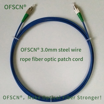
1. OFSCN® 3.0mm Steel Wire Rope Fiber Optic Patch Cord
This patch cord integrates high-strength seamless stainless steel tubes and a stranded steel wire structure. While ensuring stable optical signal transmission, it can withstand high-intensity alternating mechanical vibrations and prevent stress fatigue in the connector.
- Key Parameters:
- Outer Diameter: 3.0\ \text{mm}
- Default Connector: FC/APC (Metal Thread Lock)
- Structural Composition: Comprises fiber optic connector, PE jacket, 0.45\ \text{mm} steel wire stranded structure, 0.9\ \text{mm} seamless stainless steel tube, and optical fiber.
- Mechanical Strength: Tensile Strength > 1200\ \text{N} , Compressive Strength > 200\ \text{MPa}
- Official Link: OFSCN® 3.0mm Steel Wire Rope Fiber Optic Patch Cord
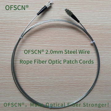
2. OFSCN® 2.0mm Steel Wire Rope Fiber Optic Patch Cord
The all-metal structure (without an outer resin protective jacket) offers excellent resistance to mechanical abrasion and exceptional overall structural stability, making it suitable for more intense vibration, high-temperature, and high-pressure harsh industrial environments.
- Key Parameters:
- Outer Diameter: 2.0\ \text{mm}
- Default Connector: FC/APC (Metal Thread Lock)
- Structural Composition: Comprises fiber optic connector, 0.6\ \text{mm} galvanized steel wire stranded structure, 1.0\ \text{mm} seamless stainless steel tube, and optical fiber.
- Operating Temperature Range: -40\ ^\circ\text{C} to 85\ ^\circ\text{C}
- Official Link: OFSCN® 2.0mm Steel Wire Rope Fiber Optic Patch Cord
IV. Engineering Recommendations for Preventing Loosening in Field Installation
Even when using vibration-resistant metal-threaded FC connectors and armored patch cords, it is still recommended to incorporate the following engineering measures during installation in extreme environments like vibrating screens or engines:
- Apply Appropriate Hand-Tightening or Tool Torque: Ensure the FC metal threaded sleeve is tightened securely during installation. This ensures the internal spring is compressed and exerts its constant preload.
- Auxiliary Use of Threadlocker or Plumber’s Tape: For exceptionally extreme vibration environments, a small amount of low-strength threadlocker (e.g., Loctite 222) can be applied to the external threads of the flange (adapter), or a loop of sealing plumber’s tape can be used to increase micro-resistance. However, strictly prevent excess adhesive from contaminating the ceramic end face.
- Establish Reasonable Cable Securing Points: Avoid letting the patch cord hang freely and be subjected to inertial pulling from vibrations. It is recommended to secure the patch cord to the main structure of the engine/vibrating screen using stainless steel clamps or zip ties at a point 10\ \text{cm} to 20\ \text{cm} away from the connector’s strain relief boot. This significantly reduces the axial and shear stress transmitted to the connector from cable swaying.